Rigidity-improved connecting rod type clamping structure

A connecting rod and holder technology, which is applied in the field of improving the rigid connecting rod clamping structure, can solve the problems of inaccurate insertion, slippage, discount of radioactive source visual positioning effect, etc., to ensure functional stability, simple and reliable structure, Effect of Reliability Improvement

Active Publication Date: 2016-05-11
BEIJING AUTOMATION CONTROL EQUIP INST
View PDF6 Cites 5 Cited by
  • Summary
  • Abstract
  • Description
  • Claims
  • Application Information

AI Technical Summary

Problems solved by technology

The clamping mechanism of the existing radioactive source is clamped by two long and narrow metal rigid rods. In the case of a long force arm, it cannot provide effective clamping force for the end clamping part, and the radioactive source cannot be in line with the clamping mechanism, resulting in When installing the radioactive source, the visual positioning effect is greatly reduced, and it cannot be inserted into the source hole accurately
At the same time, since the radioactive source, the logging instrument and the radioactive source tank are all threaded, if the clamping mechanism cannot be clamped, the effective torque cannot be provided when the radioactive source is tightened, and it will slip away.

Method used


Image

  • Rigidity-improved connecting rod type clamping structure
  • Rigidity-improved connecting rod type clamping structure
  • Rigidity-improved connecting rod type clamping structure

Examples


Embodiment Construction

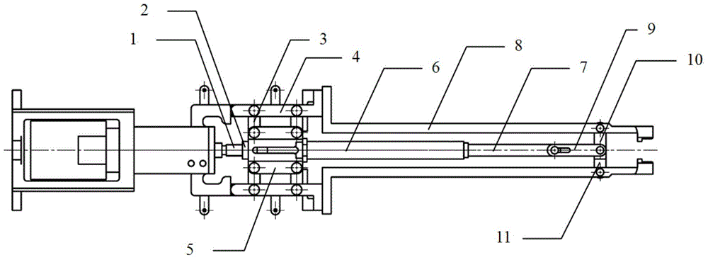
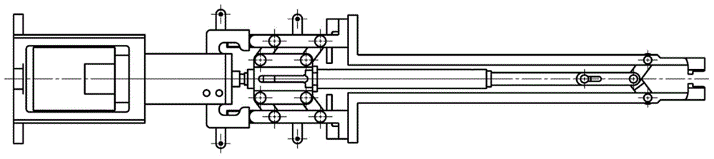
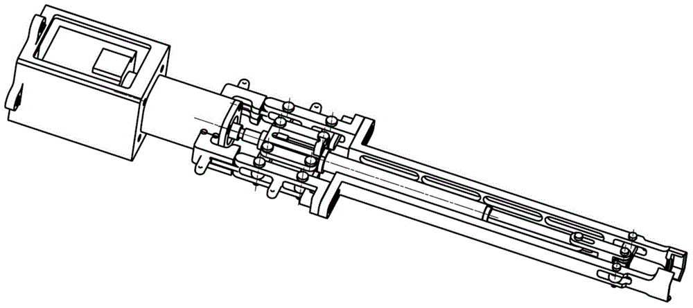
[0013] as attached figure 1 As shown, a multifunctional end gripper includes a palm 5, one end of the palm 5 is connected to a lead screw 1 through a lead screw nut 2, and the lead screw 1 is connected to the outside and controlled by an external device. The other end of the palm 5 is connected with the outer finger 8 and the inner finger bar 6, the outer finger 8 has two, these two outer fingers 8 and the inner finger bar 6 are parallel, and the inner finger bar 6 is arranged on two outer fingers. Refers to the middle of 8. When the leading screw 1 rotates, the palm 5 can convert the rotation of the leading screw 1 into clamping or loosening of the two outer fingers 8, and simultaneously control the extension or retraction of the inner finger rod 6. The front end of the inner finger rod 6 is provided with a locking link extension 7, and a locking link 9 is set at the front end of the locking link extension 7. The two outer fingers 8 are connected to the locking link 9 throu...


PUM


Abstract

The invention belongs to grippers, and particularly relates to a rigidity-improved connecting rod type clamping structure which comprises a palm, wherein one end of the palm is connected with a screw rod through a screw nut; the screw rod is connected with the external part and is controlled by an external device; the other end of the palm is connected with two outer fingers and an inner finger rod; the two outer fingers are parallel to the inner finger rod; the inner finger rod is arranged between the two outer fingers; when the screw rod rotates, the palm can convert the rotation of the screw rod to clamping or loosening of the two outer fingers, and can control the stretching or retraction of the inner finger rod; a locking connecting rod extension part is arranged at the front part of the inner finger rod; a locking connecting rod is arranged at the front end of the locking connecting rod extension part; and the two outer fingers are connected with the locking connecting rod through double connecting rods and a single connecting rod respectively. The rigidity-improved connecting rod type clamping structure has the benefits that the structure is simple and reliable, the space is compact, a plurality of groups of parallelogram connecting rod structures are placed in the narrow space, and the function stability of the integral clamping mechanism is guaranteed.

Description

technical field [0001] The invention belongs to a clamper, in particular to a link type clamping structure with improved rigidity. Background technique [0002] It is a routine operation in the process of offshore oil and gas exploration to hoist the active logging tool into the test well by hoisting it with a crane, and measure the degree of oil and gas accumulation in the formation through which the logging tool passes through the nuclear physics method. Before logging, the detection radioactive source needs to be removed from the source tank and installed on the logging tool; after logging, the radioactive source needs to be removed from the logging tool and put back into the source tank. At present, the loading and unloading process of radioactive sources is done manually. In order to reduce the harm of radioactive sources to the staff, it is very necessary to use automated source loading and unloading robots instead of workers to complete the loading and unloading proce...

Claims


Application Information

Patent Timeline
Patent Type & Authority Applications(China)
IPC IPC(8): B25J15/10
Inventor 谢铮张新华裴宏军王嘉力吕翀张明伟高恒恒
Owner BEIJING AUTOMATION CONTROL EQUIP INST
Why Eureka
Try Eureka