Offset display light machine, method thereof and near-to-eye display equipment

A near-eye display and display light technology, which is applied in optics, optical components, instruments, etc., can solve problems such as affecting perception and appearance of ghost images, and achieve the effects of compact structure, reduced overall weight, and reduced cost

Active Publication Date: 2022-07-01
SUNNY OPTICAL ZHEJIANG RES INST CO LTD +1
View PDF15 Cites 0 Cited by
  • Summary
  • Abstract
  • Description
  • Claims
  • Application Information

AI Technical Summary

Problems solved by technology

At present, among the various schemes in the field of near-eye display, the mainstream schemes include catadioptric structures (Birdbath, BB), free-form surface prisms, array optical waveguides, and diffractive optical waveguides. Among them, the waveguide-based AR mode Although the group has been widely concerned and applied due to its advantages of small size, lightness, and good experience, AR display modules based on diffractive optical waveguides usually have ghost images in the AR display screen, which affects the perception. Therefore, how to effectively reduce the It is particularly important and meaningful to eliminate ghost images in the display screen

Method used


Image

  • Offset display light machine, method thereof and near-to-eye display equipment
  • Offset display light machine, method thereof and near-to-eye display equipment
  • Offset display light machine, method thereof and near-to-eye display equipment

Examples


Embodiment Construction

[0045] The following description serves to disclose the invention to enable those skilled in the art to practice the invention. The preferred embodiments described below are given by way of example only, and other obvious modifications will occur to those skilled in the art. The basic principles of the invention defined in the following description may be applied to other embodiments, variations, improvements, equivalents, and other technical solutions without departing from the spirit and scope of the invention.

[0046] It should be understood by those skilled in the art that in the disclosure of the present invention, the terms "portrait", "horizontal", "upper", "lower", "front", "rear", "left", "right", " The orientation or positional relationship indicated by vertical, horizontal, top, bottom, inner, outer, etc. is based on the orientation or positional relationship shown in the drawings, which is only for the convenience of describing the present invention and to simpli...


PUM


Abstract

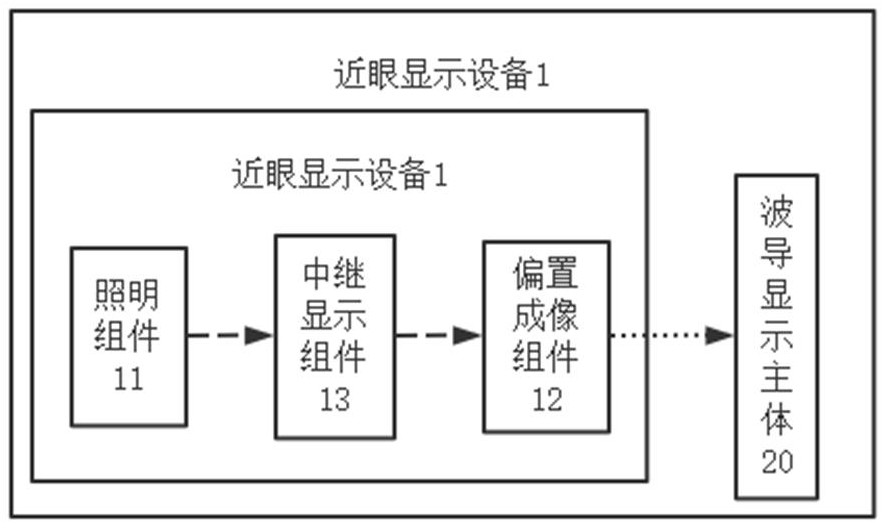
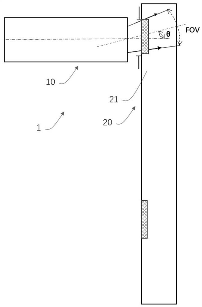
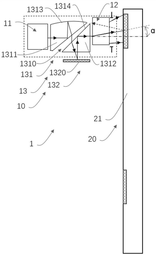
The invention provides an offset display light machine, a method thereof and near-to-eye display equipment, which can effectively reduce or eliminate ghost images in a display picture and improve the impression. The offset display light machine comprises an illumination assembly used for emitting an illumination light beam; the bias imaging assembly is used for modulating the image light beam in a deflection manner for imaging; the relay display assembly is arranged in a light path between the illumination assembly and the bias imaging assembly, and the relay display assembly is used for modulating an illumination light beam from the illumination assembly into an image light beam so as to spread the image light beam to the bias imaging assembly; the bias imaging assembly is used for deflecting the image light beam from the relay display assembly so as to obliquely project the image light beam to the coupling-in area of the waveguide display body, so that the view field of the bias display light machine is biased.

Description

technical field [0001] The present invention relates to the technical field of near-eye display, and in particular, to an offset display optical machine, a method thereof, and a near-eye display device. Background technique [0002] In recent years, with the continuous development of new display technologies, the related market for near-eye display devices (such as AR or VR glasses, etc.) has become increasingly mature. At present, among the various solutions in the field of near-eye display, the mainstream solutions include fold-back structures (Birdbath, BB), free-form surface prisms, arrayed optical waveguides, and diffractive optical waveguides. Among them, the AR mode based on the waveguide solution Although the device has been widely used due to its advantages of small size, light weight and good experience, AR display modules based on diffractive optical waveguides usually appear ghost images in the AR display screen, affecting the look and feel, so how to effectively...

Claims


Application Information

Patent Timeline
Patent Type & Authority Applications(China)
IPC IPC(8): G02B27/01
CPCG02B27/0172
Inventor 张倩陈杭郝希应
Owner SUNNY OPTICAL ZHEJIANG RES INST CO LTD
Why Eureka
Try Eureka