Garbage truck compression device

A compression device and garbage truck technology, which is applied in the field of transfer equipment and garbage treatment, can solve the problems of small material compression ratio and low filling efficiency, and achieve the effect of improving compression and avoiding leakage

Inactive Publication Date: 2016-05-11
JINLV ENVIRONMENT TECH
View PDF8 Cites 11 Cited by
  • Summary
  • Abstract
  • Description
  • Claims
  • Application Information

AI Technical Summary

Problems solved by technology

[0003] The purpose of the present invention is to provide a garbage truck compression device to solve the problems of low material compression ratio and low loading efficiency in the prior art

Method used


Image

  • Garbage truck compression device
  • Garbage truck compression device
  • Garbage truck compression device

Examples


Embodiment Construction

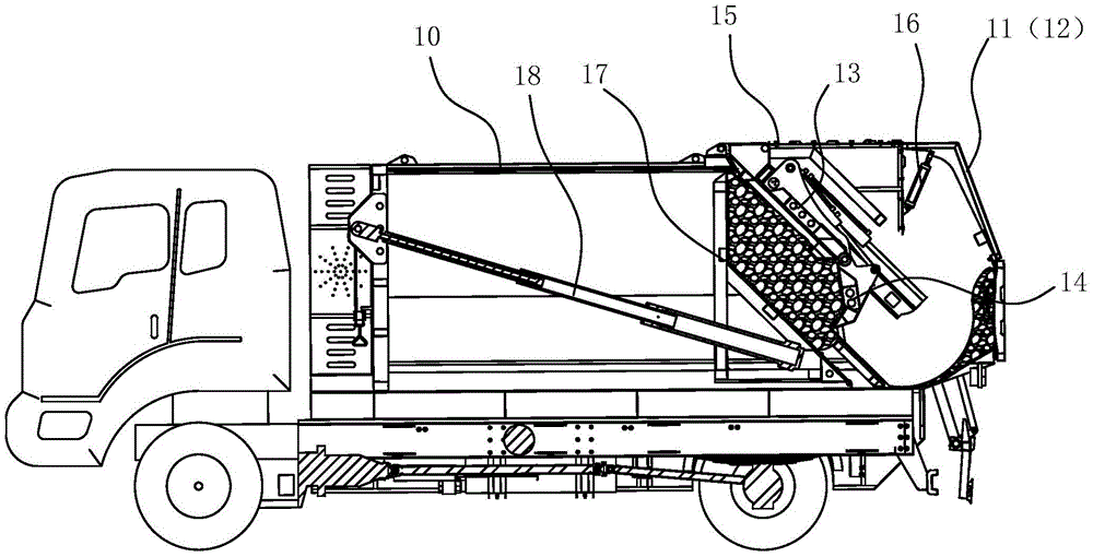
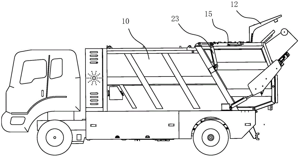
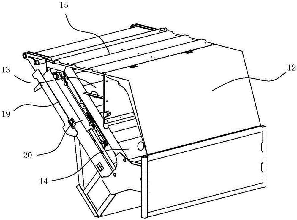
[0012] Such as figure 1 , 4 As shown, a garbage truck compression device, the compression device is located inside the inlet 11 of the garbage truck compartment 10, the compression device includes a turning mechanism and a sliding mechanism, the turning mechanism is arranged on the sliding mechanism, the turning The mechanism, the sliding mechanism, and the unloading push plate 17 in the carriage enclose a squeeze cavity for compressing garbage. The turning mechanism hooks the garbage that enters the feed inlet 11 into the squeezing cavity, and the sliding mechanism drives the turning mechanism to translate. The squeeze cavity space is reduced, and the garbage is compressed.

[0013] The unloading push plate 17 is slidably arranged in the horizontal direction, and the carriage 10 is provided with a first hydraulic cylinder 18 for driving the unloading push plate 17 to slide. During the compression process of the compression device, the first hydraulic cylinder 18 is always maintai...


PUM


Abstract

The invention belongs to garbage treatment and transfer equipment, and particularlyrelates to a garbage truck compression device. The compression device is positioned on the inner side of a feed port of a carriage of a garbage truck, and comprises anoverturningmechanism and a slide mechanism; the overturning mechanism is arranged on the slide mechanism; the overturning mechanism, the slide mechanism and an unloading push plate in the carriage are arranged in an encircling way to form an extrusion cavity for compressing garbage; the overturning mechanism hooks the garbage entering the feed port, and feeds the garbage into the extrusion cavity; and the slide mechanism drives the overturning mechanism to perform a translation motion to shrink the space of the extrusion cavityso as to compress the garbage. The garbage truck compression device adopts the overturning mechanism to hook the garbage and feed the same into the extrusion cavity, and then the slide mechanism is used for extruding the garbage; the whole extruding process can guarantee the extrusion cavity to be always kept in a better closing state to prevent the garbage from leaking out of the extrusion cavity so as to guarantee the extrusion cavity to possess enough pressure,and therefore the compression and filling efficiency of the garbage truck compression device is improved.

Description

Technical field [0001] The invention belongs to garbage treatment and transfer equipment, and specifically relates to a garbage truck compression device. Background technique [0002] The compression device in the prior art mainly includes a compression storage box and a compression device. Take a garbage truck as an example: the garbage truck includes a chassis and a compression storage box. The back of the compression storage box is provided with a feeding mechanism and a compression device. A push plate is also arranged inside the material box. The main working process is as follows: First, the feeding mechanism lifts and turns the trash can to dump the trash into the inlet of the compression storage bin, and then presses the trash roll into the compression storage bin through the turning movement of the compression device until the storage bin is compressed. Was filled with garbage. When unloading, the compression device is fully opened, and the push plate in the compressio...

Claims


Application Information

Patent Timeline
Patent Type & Authority Applications(China)
IPC IPC(8): B65F3/20
CPCB65F3/201
Inventor 姚喜姜琳吕洪林莫永新
Owner JINLV ENVIRONMENT TECH
Why Eureka
Try Eureka