Eureka AIR delivers breakthrough ideas for toughest innovation challenges, trusted by R&D personnel around the world.

Improved floor brick

A technology of floor tiles and frames, applied in the field of floor tiles, can solve the problems of weakened bonding force between floor tiles and the ground, loose floor tiles, easy deformation of pedestrians, etc., and achieves the effect of quick laying and clean walking.

Active Publication Date: 2016-05-11
徐州博创建设发展集团有限公司
View PDF6 Cites 6 Cited by
  • Summary
  • Abstract
  • Description
  • Claims
  • Application Information

AI Technical Summary

Problems solved by technology

[0002] When planning streets, floor tiles are often laid on the surface of the street. On the one hand, the floor tiles can beautify the street. Most of the time, cement mortar is used to level the ground first, and then the floor tiles are directly laid on the street surface. Because the soil layer under the cement mortar layer is soft, it is easy to deform after being eroded by rain for a long time and pedestrians stepping on it for a long time. Concave-convex deformation occurs on the surface, which leads to poor stability of the floor tiles and weakens the bonding force between the floor tiles and the ground; this causes the floor tiles to loosen; in rainy weather, rainwater accumulates in the depression between the ground and the floor tiles, once pedestrians Stepping on loose floor tiles, the rainwater and sludge accumulated under the floor tiles will suddenly splash and wet and pollute the pants of pedestrians. This phenomenon has become a problem of floor tiles in streets and squares in major cities; and there is still no effective way to solve it. This problem, so the street floor tiles in major cities can only be continuously maintained, removed and resurfaced; in summary, this kind of floor tiles not only has relatively large defects, but also consumes more costs in later maintenance

Method used


Image

  • Improved floor brick
  • Improved floor brick
  • Improved floor brick

Examples


Embodiment

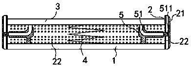
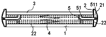
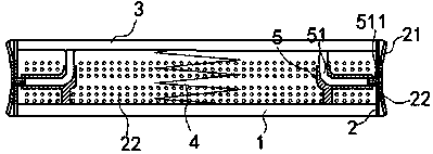
[0013] exist Figure 1 to Figure 3 In the shown embodiment, the improved floor tile includes a base 1, a shaped frame 2 and a top plate 3; the shaped frame 2 is fixedly mounted on the base 1, and the top plate 3 is movably buckled on the shaped frame 2 , the top plate 3 can translate up and down along the side wall of the shaped frame 2, and a return spring 4 is also installed between the base 1 and the top plate 3; an elastic material is wrapped outside the shaped frame 2 The formed deformable membrane 21 is provided with diversion holes 22 equidistantly on the shaped frame 2 and the deformable membrane 21, and the aperture direction of each diversion hole 22 is 45 degrees obliquely downward to the horizontal direction; The center of the four corners of the base 1 is symmetrically fixed with L-shaped guide tube holders 5, one nozzle of each guide tube holder 5 is vertically facing the top plate 3, and one nozzle is horizontally facing the shaped frame 2; an adjustment rod 51...


PUM


Abstract

The invention relates to an improved floor brick which comprises a base, a shaping frame and a top plate. The top plate is movably fastened on the shaping frame, and a return spring is further mounted between the base and the top plate; a deformation film made of elastic materials wraps the outside of the shaping frame, and flow guide holes are equidistantly formed in the shaping frame and the deformation film; L-shaped guide pipe seats are centrally symmetrically fixed onto four corners of the base, a pipe orifice of each guide pipe seat vertically and upwardly directly faces the top plate, and the other pipe orifice of each guide pipe seat horizontally directly faces the shaping frame; adjusting rods are mounted in the various guide pipe seats; one end of each adjusting rod is fixedly connected onto the top plate, and permanent magnetic columns are fixedly mounted at the other ends of the adjusting rods, penetrate the shaping frame and are adhered onto the deformation film. The improved floor brick has the advantages that the improved floor brick is novel in structure and convenient to lay and maintain, and rainwater can be effectively prevented from splashing.

Description

technical field [0001] The present invention relates to a street paving material, in particular to a floor tile. Background technique [0002] When planning streets, floor tiles are often laid on the surface of the street. On the one hand, the floor tiles can beautify the street. Most of the time, cement mortar is used to level the ground first, and then the floor tiles are directly laid on the street surface. Because the soil layer under the cement mortar layer is soft, it is easy to deform after being eroded by rain for a long time and pedestrians stepping on it for a long time. Concave-convex deformation occurs on the surface, which leads to poor stability of the floor tiles and weakens the bonding force between the floor tiles and the ground; this causes the floor tiles to loosen; in rainy weather, rainwater accumulates in the depression between the ground and the floor tiles, once pedestrians Stepping on loose floor tiles, the rainwater and sludge accumulated under t...

Claims


Application Information

Patent Timeline
IPC IPC(8): E01C15/00
Inventor 胡振强
Owner 徐州博创建设发展集团有限公司
Why Eureka
Eureka Blog
Learn More