Eureka AIR delivers breakthrough ideas for toughest innovation challenges, trusted by R&D personnel around the world.

Sound dampening device

Active Publication Date: 2016-03-10
ARTEX LTD
View PDF6 Cites 4 Cited by
  • Summary
  • Abstract
  • Description
  • Claims
  • Application Information

AI Technical Summary

Benefits of technology

The present invention is a sound dampening device that improves the indoor environment in multiple ways. It includes a frame, a rear layer, and a front layer, with a cavity in between. An air purifying device is integrated with the cavity, providing an air purifying function as well as a sound dampening function. The distribution layer is made of cellular plastic with high permeability, which allows the purified air to spread and be distributed over a larger area, resulting in a cost-effective and efficient air purifying sound dampening device. The invention also includes an inlet and an outlet for the purified air, with a low flow rate to avoid draught and create a comfortable local environment. The distribution layer has a high permeability, low flow resistance, and low noise level, and the invention also provides a functional headboard with speakers, sockets, and other integrated functions.

Problems solved by technology

Poor acoustic properties in an indoor environment may specifically affect people's cognitive and communicative abilities.
Consequences of poor acoustic environments may be attention problems, concentration problems, reduced ability to learn, lower quality of performed work and lower productivity.
At higher sound levels there might also be a risk of temporary or permanent hearing impairment, tinnitus, health problems and stress.
The indoor air quality may also affect people's health.
Poor air quality may cause asthma, allergies, symptoms in the eyes, the nose and on the skin, fatigue and headache.
While these devices solve one problem, they may cause another problem.
For example, a separate air purifier might be visually disturbing and cause unpleasant air flows, draught, high noise levels and might even be standing in the way.
Some sound absorbing solutions may also cause problems, such as hindering ventilation and collecting of dust, particles and microorganisms.
This is however a complex and costly solution which complicates maintenance and service of the air-conditioner.
The arrangement is large and bulky.

Method used


Image

  • Sound dampening device
  • Sound dampening device
  • Sound dampening device

Examples


Embodiment Construction

[0048]The present invention will now be described as embodiments. For clarity, the components irrelevant to the invention have been omitted in the drawing. The same details as shown in several drawings may sometimes lack reference numerals, but correspond to those with reference numerals.

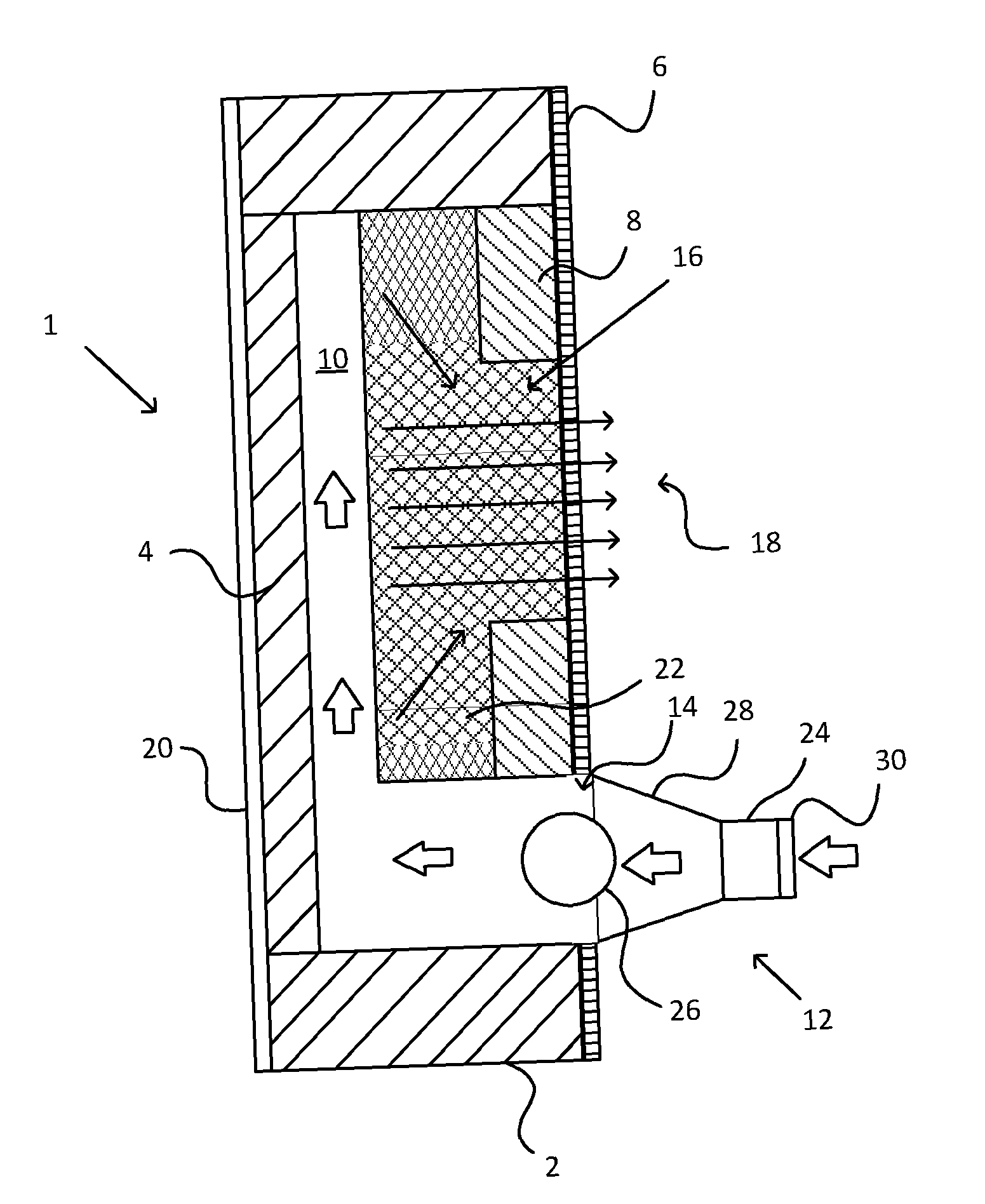
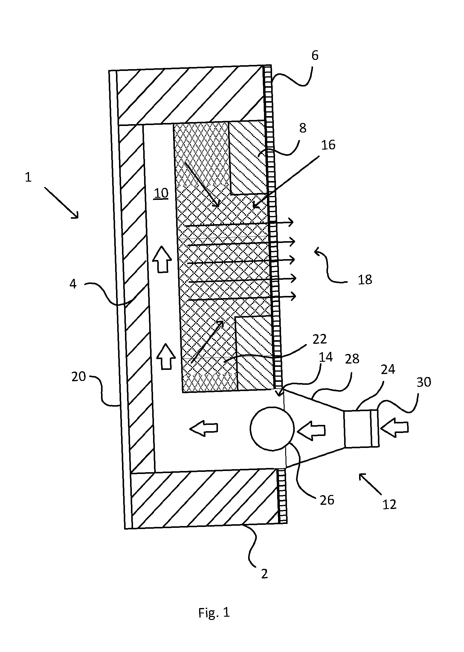
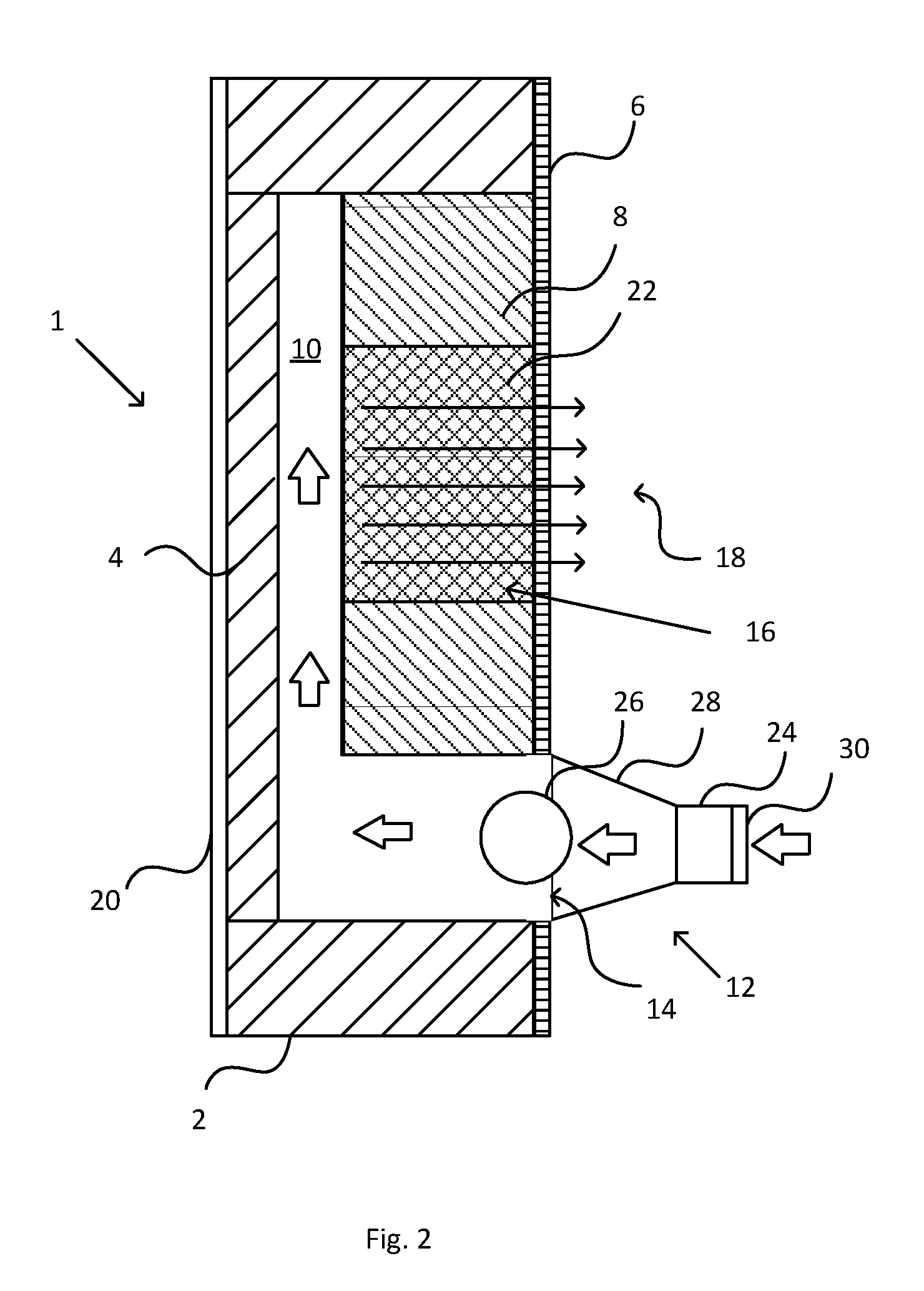
[0049]FIG. 1 shows a cross-sectional side view of a sound dampening device 1 according to an embodiment of the present invention. The sound dampening device 1 comprises a frame 2, a rear layer 4 and a front layer 6 arranged on opposite sides of the frame 2, such that the frame 2, the rear layer 4 and the front layer 6 forms an enclosed space. A first sound absorbing layer 8 is also arranged between the rear layer 4 and the front layer 6 wherein a cavity 10 is formed between the rear layer 4 and the first sound absorbing layer 8. An air purifying device 12 is arranged in fluid communication with the cavity 10, such that purified air from the air purifying device 12 is supplied to the cavity 10 via an...


PUM


Abstract

The invention relates to a sound dampening device (1) comprising a frame (2), a rear layer (4) and a front layer (6) arranged on opposite sides of the frame (2), such that the frame (2), the rear layer (4) and the front layer (6) forms an enclosed space, wherein a first sound absorbing layer (8) is arranged between the rear layer (4) and the front layer (6). A cavity (10) is formed between the rear layer (4) and the first sound absorbing layer (8) and an air purifying device (12) is arranged in fluid communication with said cavity (10), such that purified air from the air purifying device (12) is supplied to the cavity (10) via an inlet (14) and is discharged through at least one opening (16) in the first sound absorbing layer (8) and at least one output zone (18) in the front layer (6).

Description

TECHNICAL FIELD[0001]The present invention relates to a sound dampening device. The invention may be attributed to the manufacturing industry of sound dampening devices.BACKGROUND[0002]Various devices are today used to improve the indoor environment in for example offices, public buildings, schools, hospitals and exhibition areas or similar. The indoor environment may affect peoples' health, their quality of life, comfort, ability to learn and productivity. This is specifically a fact in colder climates where people tend to spend more time indoors. Factors that may affect the indoor environment are air quality, thermal comfort, acoustic properties and the visual quality.[0003]Poor acoustic properties in an indoor environment may specifically affect people's cognitive and communicative abilities. Consequences of poor acoustic environments may be attention problems, concentration problems, reduced ability to learn, lower quality of performed work and lower productivity. At higher soun...

Claims


Application Information

Patent Timeline
IPC IPC(8): A47C19/02A47C31/00F24F13/24
CPCA47C19/022A47C31/00F24F13/24G10K11/161G10K11/162G10K11/172A61L9/20A61L2209/14
Inventor RYDSUND, MATS
Owner ARTEX LTD
Why Eureka
Eureka Blog
Learn More