Electronic Device

a technology of electronic devices and liquid crystal displays, applied in the direction of portable computers, charging/discharging current/voltage regulation, instruments, etc., can solve the problems of secondary battery weight, power consumption might increase, and it is difficult to achieve both an increase in visibility in outdoor and indoor environments and a reduction of power consumption in liquid crystal display devices. , to achieve the effect of high portability, high convenience and high visibility

Active Publication Date: 2017-11-02
SEMICON ENERGY LAB CO LTD
View PDF10 Cites 11 Cited by
  • Summary
  • Abstract
  • Description
  • Claims
  • Application Information

AI Technical Summary

Benefits of technology

[0005]An electronic device provided with a display device including a solar battery is assumed to be used in outdoor environments or indoor environments. When the electronic device is used in outdoor environments and a reflective liquid crystal display device is employed as the display device, the visibility in outdoor environments can be improved; however, the visibility in indoor environments might be decreased. When the electronic device is used in indoor environments utilizing a secondary battery as a power source and a transmissive liquid crystal display device or a display device including a self-luminous element (a light-emitting device) is employed as the display device, the visibility in indoor environments can be improved; however, the visibility in outdoor environments might be decreased. When a semi-transmissive liquid crystal display device is used as the display device, the visibility in indoor environments and outdoor environments are improved to some extent; however, the power consumption might be increased because a backlight emits light uniformly at the back surface of a liquid crystal element.
[0006]To increase the convenience of the electronic device for the use in outdoor environments or indoor environments, it is effective to improve carrying easiness (portability). To improve portability, reduction in the weight of the electronic device, particularly the secondary battery, is effective. However, it is difficult to achieve both an increase in visibility in outdoor and indoor environments and a reduction in power consumption in a liquid crystal display device or a light-emitting device, and to reduce the weight of the secondary battery.
[0007]An object of one embodiment of the present invention is to provide an electronic device which includes a solar battery and a display device with high visibility in outdoor and indoor environments.
[0008]Another object of one embodiment of the present invention is to provide an electronic device which includes a solar battery and a display device with high convenience, in particular high portability.
[0019]One embodiment of the present invention provides an electronic device which includes a solar battery and a display device with high visibility in outdoor and indoor environments.
[0020]One embodiment of the present invention provides an electronic device which includes a solar battery and a display device with high convenience, in particular high portability.

Problems solved by technology

When a semi-transmissive liquid crystal display device is used as the display device, the visibility in indoor environments and outdoor environments are improved to some extent; however, the power consumption might be increased because a backlight emits light uniformly at the back surface of a liquid crystal element.
However, it is difficult to achieve both an increase in visibility in outdoor and indoor environments and a reduction in power consumption in a liquid crystal display device or a light-emitting device, and to reduce the weight of the secondary battery.

Method used


Image

  • Electronic Device
  • Electronic Device
  • Electronic Device

Examples


modification example 1

Electronic Device 10A

[0151]FIG. 11A is a perspective view seen from one surface (a front surface) side of the electronic device 10A. FIG. 12A is a perspective view seen from the other surface (a rear surface) side of the electronic device 10A. FIGS. 11B, 11C, 12B, and 12C show examples of the electronic device 10A which is changed in form.

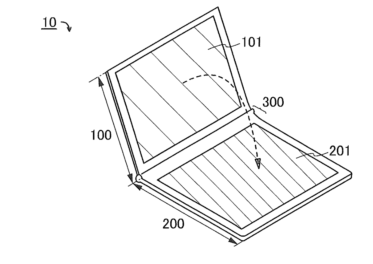
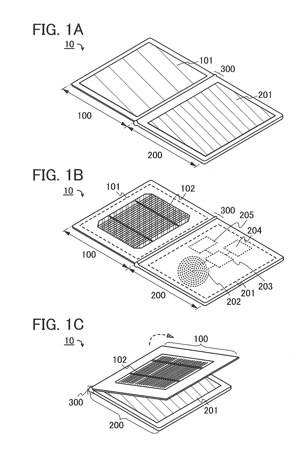
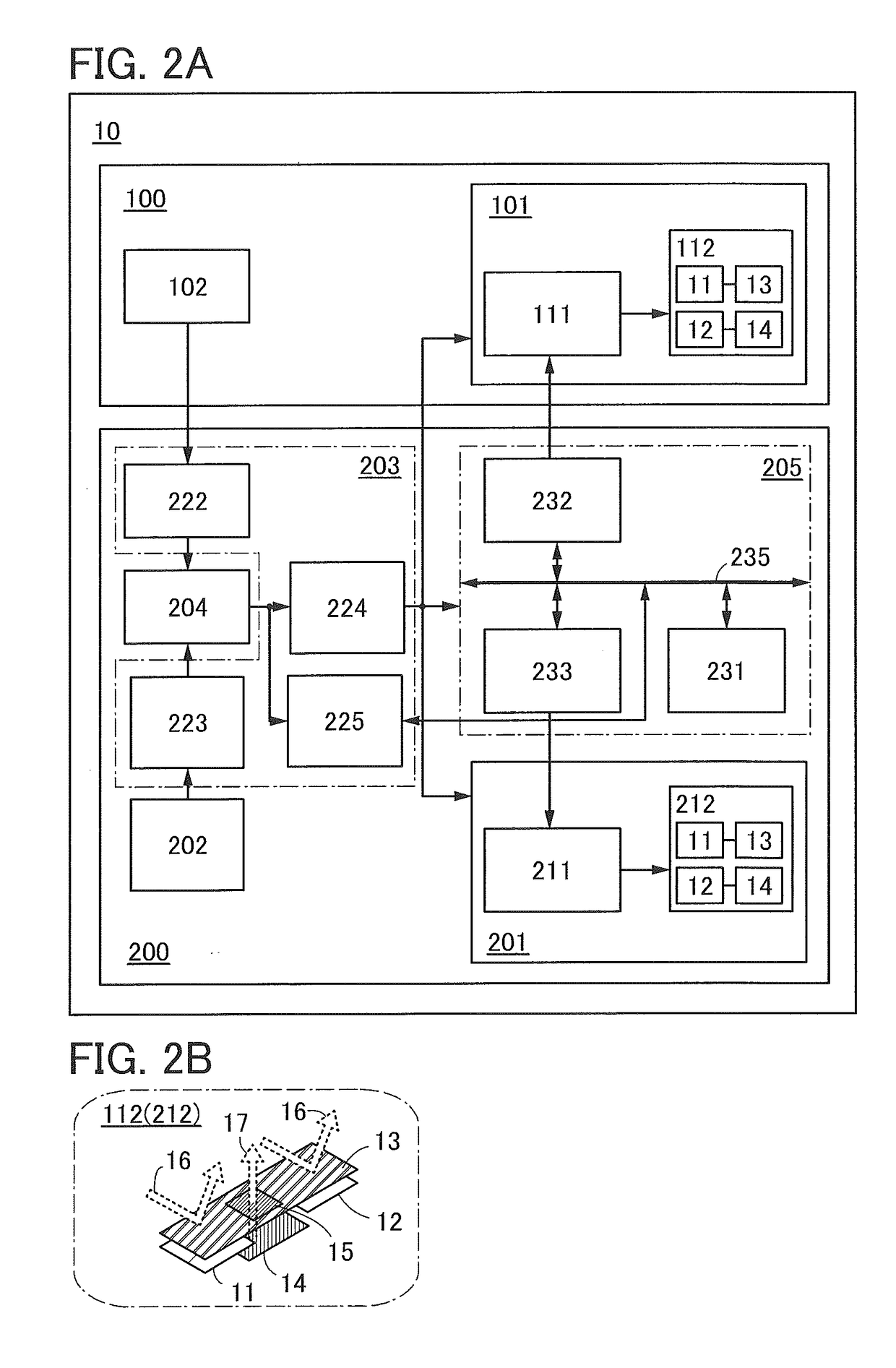
[0152]The electronic device 10A includes, like the electronic device 10, the housing 100 and the housing 200. The housing 100 includes the display device 101 on the front surface side and the solar battery 102 on the rear surface side. The housing 200 includes the display device 201 on the front surface side. The housing 200 includes the coil 202, the charge and discharge control circuit 203, the electric double-layer capacitor 204, and the signal processing circuit 205 inside.

[0153]The electronic device 10A includes a hinge portion 300. The electronic device 10A can be folded so that a front surface side of the housing 100 and a front surface side...

modification example 2

Electronic Device 10B

[0162]FIG. 15A is a perspective view seen from one surface (a front surface) side of the electronic device 10B. FIG. 15B shows an example of the electronic device 10B which is changed in form.

[0163]The shapes of the structure bodies 131a and 131b are not particularly limited. For example, the shapes of the structure bodies 131a and 131b may be circular, elliptical, rectangular, polygonal, or the like when seen in the plan view. Alternatively, the structure bodies 131a and 131b may each have a shape in which a curve line and a straight line are combined.

[0164]As illustrated in FIGS. 15A and 15B, a linear structure body 131c may be provided along an outer edge of the housing 100 on the front surface side. Similarly, the linear structure body 131c may be provided along an outer edge of the housing 200 on the front surface side. Although not illustrated, the structure body 131c may be provided on the rear surface sides of the housing 100 and the housing 200. When th...

modification example 3

Electronic Device 10C

[0165]FIG. 16A is a perspective view seen from one surface (a front surface) side of the electronic device 10C. FIGS. 16B and 16C show examples of the electronic device 10C which is changed in form.

[0166]When a display device is provided in each of the housings 100 and 200 and an image is displayed in the state where an electronic device is opened, a cut is provided in the image displayed on a display region. Thus, in the electronic device 10C, instead of the display device 101 and the display device 201, a display device 251 that extends over the housing 100 and the housing 200 is provided. As a result, the display device 251 includes a region overlapping with the housing 100 and a region overlapping with the housing 200.

[0167]The display device 251 has flexibility. Since the display device 251 has flexibility, the display device 251 can be provided across a region between the housing 100 and the housing 200. Moreover, the display device is not easily damaged e...


PUM

PropertyMeasurementUnit
Young's modulusaaaaaaaaaa
sizeaaaaaaaaaa
frequencyaaaaaaaaaa

Abstract

The electronic device includes a first housing including a solar battery, a first display device, and a first structure body and a second housing including a second display device, a coil, an electric double-layer capacitor, a signal processing circuit, a charge and discharge control circuit, and a second structure body. The electronic device can be folded so that display surfaces of the first housing and the second housing face each other and the first structure body and the second structure body face each other. The solar battery is provided on a surface of the first housing on the rear side of the first display device. A pixel included in the first display device and a pixel included in the second display device each include a liquid crystal element, a first pixel circuit, a light-emitting element, and a second pixel circuit. The liquid crystal element includes a reflective electrode having an opening and can perform display by reflecting external light. The light-emitting element can perform display by emitting light toward the display surface through the opening.

Description

BACKGROUND OF THE INVENTION1. Field of the Invention[0001]One embodiment of the present invention relates to an electronic device.2. Description of the Related Art[0002]Electronic devices provided with display devices are widely used. When such an electronic device is carried around, a secondary battery is used as a power source. Extension of a power supply period by the secondary battery is effective for using the electronic device in outdoor environments for a long time.[0003]Patent Document 1 discloses an electronic device provided with a solar battery which can charge a secondary battery even in outdoor environments to extend a power supply period by the secondary battery.REFERENCEPatent Document[0004][Patent Document 1] United States Patent Application Publication No. 2012 / 120047SUMMARY OF THE INVENTION[0005]An electronic device provided with a display device including a solar battery is assumed to be used in outdoor environments or indoor environments. When the electronic devi...

Claims


Application Information

Patent Timeline
Patent Type & Authority Applications(United States)
IPC IPC(8): G09G3/36G02F1/1335H02J7/00G06F1/16G02F1/133G02F1/1333H02J7/35H01G11/00H02J7/34
CPCG09G3/3611H02J7/345G06F1/1647G06F1/1616G02F1/133553G02F1/13338G06F1/1643H02J7/0068H02J7/0047H02J7/007H02J7/35H01G11/00G02F2001/13324G02F2202/10G09G2360/144G09G2330/021G02F1/13318G02F1/133555G09G3/32G02F2201/44H01G11/14G06F1/1677G06F1/188H02J50/10Y02E10/56Y02E60/13G02F1/13324G02F1/133626
Inventor YAMAZAKI, SHUNPEIMIYAGUCHI, ATSUSHI
Owner SEMICON ENERGY LAB CO LTD
Why Eureka
Try Eureka