Main shaft mounting structure of rear-drive transmission

A technology for installation structure and transmission, which is applied in the directions of transmission parts, belts/chains/gears, mechanical equipment, etc., to achieve the effect of convenient and easy assembly, low cost, and reducing the risk of thread tolerance effects

Active Publication Date: 2016-05-11
CHONGQING TSINGSHAN IND
View PDF6 Cites 3 Cited by
  • Summary
  • Abstract
  • Description
  • Claims
  • Application Information

AI Technical Summary

Problems solved by technology

[0008] The technical problem to be solved by the present invention is to provide a main shaft bearing installation structure of a rear drive transmission that is relatively easy to assemble, easy to adjust the clearance and low in cost;

Method used


Image

  • Main shaft mounting structure of rear-drive transmission
  • Main shaft mounting structure of rear-drive transmission

Examples


Embodiment Construction

[0016] The present invention will be further described in detail below in conjunction with the accompanying drawings and specific embodiments.

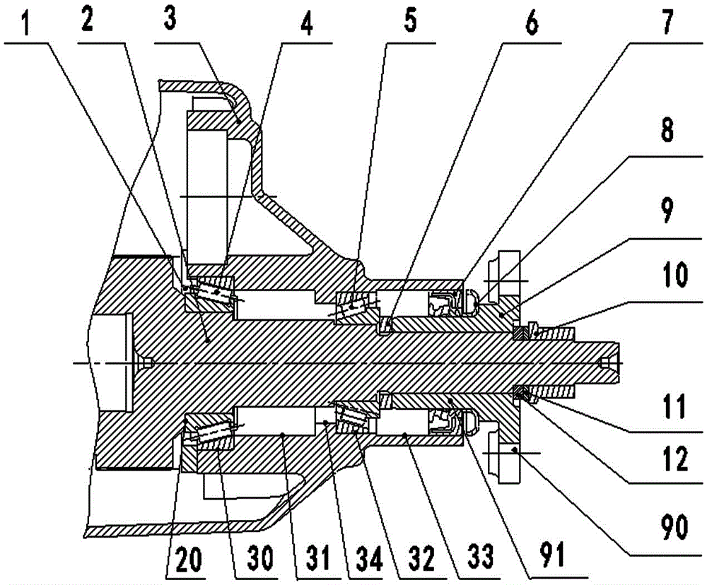
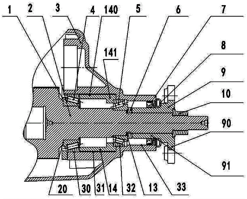
[0017] see figure 2 The main shaft installation structure of the rear drive transmission of the present invention includes a front bearing pressure plate 1, a main shaft 2, a front bearing assembly hole 30, a transition assembly hole 31, which are arranged from front to back and coaxial, and communicate with each other. Spindle case body 3 with rear bearing assembly hole 32 and flange assembly hole 33, front bearing 4, rear bearing 5, retaining ring 6, oil seal 7, dust cover 8, flange 9 and lock nut 10 all of which are taper bearings The front end of the main shaft 2 is provided with a front bearing stopper 20 protruding radially outward from the shaft body of the main shaft 2, and the flange 9 includes a disc body 90 and is integrated with the disc body 90 and formed by the The sleeve body 91 extending forward on one side of the di...


PUM


Abstract

The invention provides a main shaft mounting structure of a rear-drive transmission. The main shaft mounting structure is quite easy to assemble. The main shaft mounting structure comprises a front bearing pressing plate and a main shaft. The main shaft mounting structure is internally provided with a main shaft box body, a front bearing, a rear bearing, a retainer ring, an oil seal, a dustproof cover, a flange and a lock nut, wherein a front bearing assembling hole, a transition assembling hole, a rear bearing assembling hole and a flange assembling hole are concentrically formed in the main shaft box body from front to rear and are mutually through, and the front bearing and the rear bearing are conic bearings. The main shaft mounting structure further comprises a bearing spacer bush. The bore diameter of the front bearing assembling hole and the transition assembling hole in the main shaft box body are the same and larger than that of the rear bearing assembling hole, and the bore diameter of the rear bearing assembling hole is larger than that of the flange assembling hole. The bearing spacer bush comprises a spacer bush body with the outer diameter similar to the bore diameter of the transition assembling hole and a limiting portion which is integrally formed with the spacer bush body and annularly protrudes inwards in the radial direction. A body of the main shaft surrounding the bearing spacer bush is assembled into the transition assembling hole in the main shaft box body in the radial direction. The front end of the bearing spacer bush abuts against the rear end face of the front bearing, and the rear end of the limiting portion of the bearing spacer bush abuts against the front end face of the rear bearing.

Description

technical field [0001] The invention relates to a structure of a rear drive transmission, in particular to a main shaft installation structure of the rear drive transmission. Background technique [0002] see figure 1 , a main shaft installation structure of a rear drive transmission currently used on the market, including a main shaft 2, a front bearing pressure plate 1, a main shaft housing 3, a front bearing 4, a rear bearing 5, a retaining ring 6, an oil seal 7, and a taper bearing. Dust cover 8, flange 9, adjusting nut 12, anti-rotation washer 11 and lock nut 10; the front end of the main shaft 2 is provided with a front bearing stopper protruding radially outward from the shaft body of the main shaft 2 20, the spindle housing 3 is provided with a radially inward annular protruding rear bearing stopper 34, and the spindle housing 3 is provided with concentric, interpenetrating and sequentially decreasing apertures from front to rear. Front bearing assembly hole 30, tr...

Claims


Application Information

Patent Timeline
Patent Type & Authority Applications(China)
IPC IPC(8): F16H57/022F16H57/029
CPCF16H57/022F16H57/029F16H2057/02086F16H2057/0221
Inventor 李小粉唐祥华陈方彭天河罗会兵吕兵舒玉春邓涛李益华
Owner CHONGQING TSINGSHAN IND
Why Eureka
Try Eureka