
Finned tube

A finned tube and water tube technology, applied in the field of heat dissipation accessories, can solve the problems of short life, general heat dissipation effect, poor corrosion resistance, etc., and achieve the effects of low manufacturing cost, simple structure, and improved heat dissipation efficiency

Inactive Publication Date: 2016-05-11
天津市鼎金鼎财科技有限公司
View PDF0 Cites 2 Cited by
  • Summary
  • Abstract
  • Description
  • Claims
  • Application Information

AI Technical Summary

Problems solved by technology

[0002] At present, there are many kinds of heat dissipation pipes used for heat exchange in the market. The common heat dissipation pipes are mostly fins fixed on the base pipe alone, resulting in general heat dissipation effect, short service life and poor corrosion resistance.

Method used


Image

  • Finned tube

Examples


Embodiment Construction

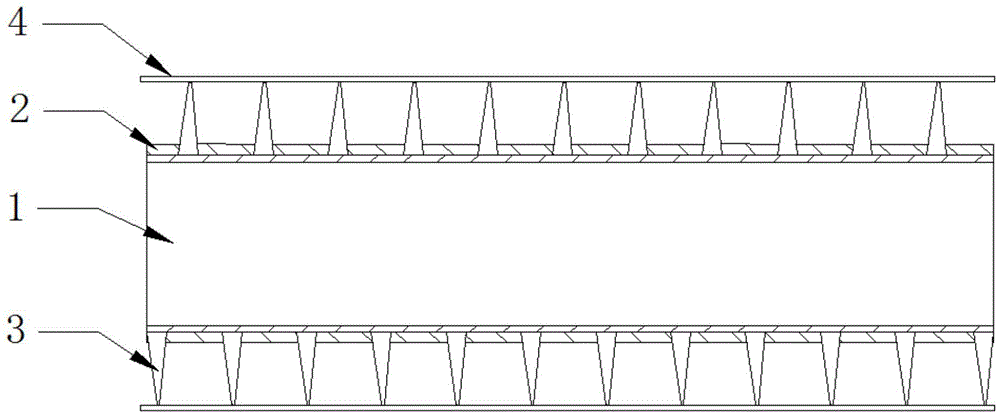
[0012] A finned tube, comprising a base pipe 1, an anti-corrosion layer 2, a heat sink 3, and a water pipe 4, the base pipe 1 is provided with an anti-corrosion layer 2, the outside of the anti-corrosion layer 2 is provided with uniformly wound heat sinks 3, and the top of the heat sink 3 is provided with There are water pipes4.

[0013] Further, the material of the anti-corrosion layer 2 is a corrosion-resistant cement coating.

[0014] Further, there are 4 water pipes 4 in total.

[0015] The embodiments of the present invention have been described in detail above, but the content described is only a preferred embodiment of the present invention and cannot be considered as limiting the implementation scope of the present invention. All equal changes and improvements made according to the creative scope of the present invention should still belong to the scope covered by this patent.


PUM


Abstract

The invention provides a finned tube. The finned tube comprises a base tube, an anti-corrosion layer, cooling fins and water tubes, wherein the outer surface of the base tube is evenly coated with the anti-corrosion layer, the platy cooling fins evenly wind around the outer part of the anti-corrosion layer by the aid of winding equipment, and the cooling water tubes are erected at top ends of the cooling fins. The finned tube is simple in structure and low in production cost, the anti-corrosion performance and the service life of the finned tube can be guaranteed, the cooling efficiency is improved, and the effect is significant.

Description

technical field [0001] The invention relates to the field of heat dissipation accessories, in particular to a finned tube. Background technique [0002] At present, there are many kinds of cooling tubes used for heat exchange in the market. Most of the common cooling tubes have fins fixed on the base tube alone, resulting in average cooling effect, short service life and poor corrosion resistance. Contents of the invention [0003] The problem to be solved by the present invention is: to overcome the deficiencies of the prior art, to design a finned tube with simple structure and low cost, the heat sink is integrally wound on the base tube and the water pipe is erected to improve the heat dissipation efficiency, and an anti-corrosion layer is added. Improve anti-corrosion efficiency and prolong service life. [0004] In order to solve the above-mentioned technical problems, the technical scheme adopted by the invention is: including base pipe, anti-corrosion layer, heat s...

Claims


Application Information

Patent Timeline
Patent Type & Authority Applications(China)
IPC IPC(8): F28F1/36F28F19/00
Inventor 刘晓东
Owner 天津市鼎金鼎财科技有限公司
Learn More