Metal part additive manufacturing method and corresponding equipment

A technology of additive manufacturing and metal parts, which is applied in the field of direct manufacturing of metal parts based on additive manufacturing technology, which can solve the problems of poor tensile strength of metal parts, low material utilization rate, and low strength of parts, so as to ensure dimensional control High precision, simple and practical structure, low energy consumption

Inactive Publication Date: 2019-04-02
INST OF IND TECH GUANGZHOU & CHINESE ACADEMY OF SCI
View PDF5 Cites 9 Cited by
  • Summary
  • Abstract
  • Description
  • Claims
  • Application Information

AI Technical Summary

Problems solved by technology

The material utilization rate of LOM technology is low, the tensile strength of the manufactured metal parts is poor, and the surface of the parts has step texture
3DP printing uses the liquid binder sprayed by the nozzle to bond the metal powder laid on the powder bed to form, and the strength of the part is very low
The printing process of SLM and SLS is very similar, the difference is that SLM uses

Method used


Image

  • Metal part additive manufacturing method and corresponding equipment
  • Metal part additive manufacturing method and corresponding equipment
  • Metal part additive manufacturing method and corresponding equipment

Examples


Embodiment 1

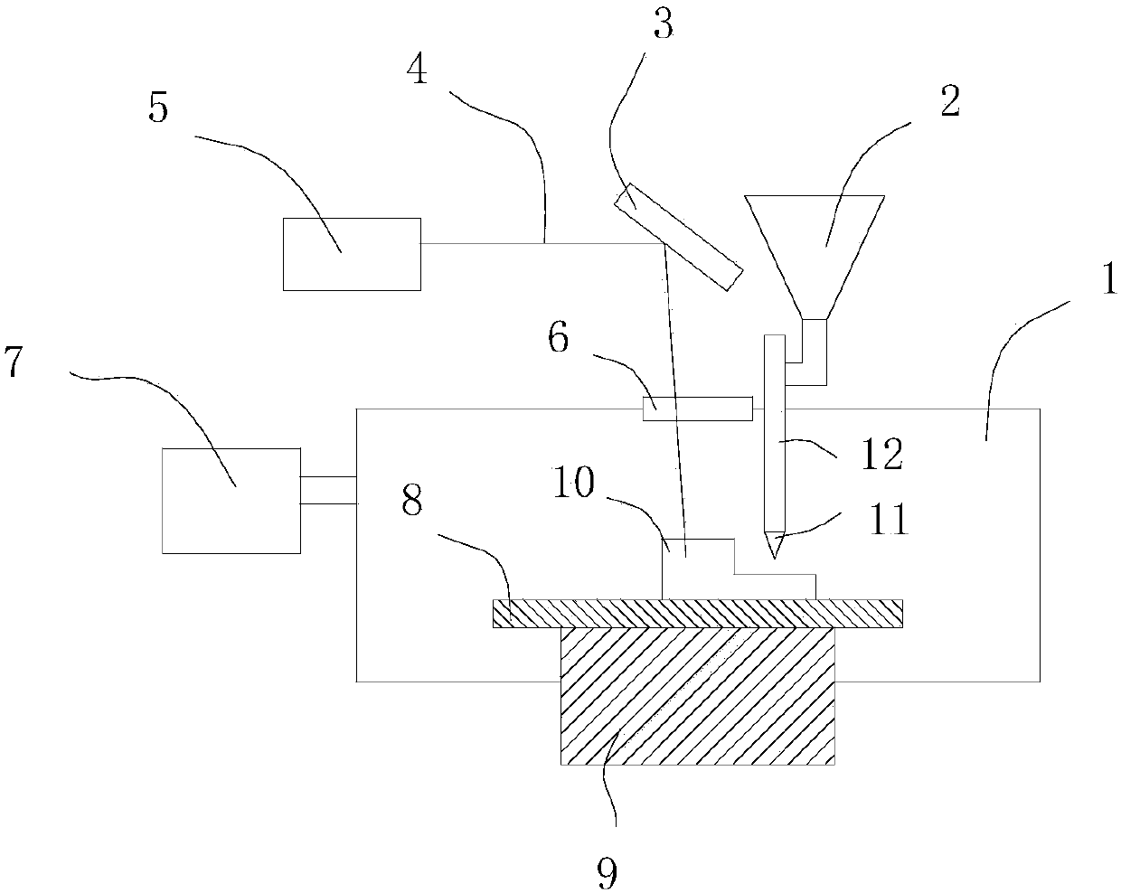
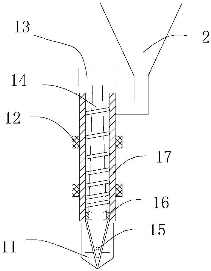
[0026] refer to figure 1, is an additive manufacturing device for metal parts, including a 3D printer with a molding cavity system, a workbench system and a control system, and a feeding system and a laser heating system respectively connected to the control system, wherein the workbench system includes The horizontal platform 8 of the forming part 10 and the lifting mechanism 9 that controls the movement of the horizontal platform 8 up and down, the feeding system includes a feeding funnel 2, a nozzle 11 arranged in the molding cavity 1, and a feeding heating device 12 arranged on the nozzle 11 , the laser heating system includes a laser 5 arranged outside the molding cavity system, and a scanning system 3 for reflecting the laser beam 4 generated by the laser 5 onto the molding part 10 . The molding cavity 1 of the 3D printer is provided with a vacuum-filled protective gas device 7, which can provide a relatively closed environment for 3D printing and sintering. In order to...

Embodiment 2

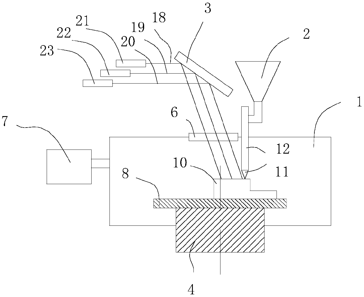
[0035] refer to image 3 , is another metal parts additive manufacturing device, including a 3D printer with a molding cavity system, a workbench system and a control system, and a feeding system and a laser heating system respectively connected to the control system, wherein the workbench system includes The horizontal platform 8 for accommodating the molding parts 10 and the lifting mechanism 9 for controlling the movement of the horizontal platform 8 up and down, the feeding system includes the feeding funnel 2, the nozzle 11 arranged in the molding cavity 1, and the feeding heating device arranged on the nozzle 11 12. The laser heating system includes a preheating laser 21, a degreasing laser 22, and a sintering laser 23 arranged outside the molding cavity system, and a preheating laser beam 18 generated by the preheating laser 21, degreasing laser 22, and sintering laser 23, The degreasing laser beam 19 and the sintering laser beam 20 are respectively reflected to the sca...

Embodiment 3

[0043] refer to Figure 4 , an additive manufacturing device for metal parts, including a 3D printer with a molding cavity system, a workbench system and a control system, and a feeding system and a gas heating system respectively connected to the control system, wherein the workbench system includes a container The horizontal platform 8 of the molding part 10 and the lifting mechanism 9 that controls the movement of the horizontal platform 8 up and down, the feeding system includes a feeding funnel 2, a nozzle 11 arranged in the molding cavity 1, a feeding heating device 12 arranged on the nozzle 11, The gas heating system includes a gas heat source 24 arranged outside the molding cavity system, a gas passage 27 extending into the molding chamber 1 , and a shroud 28 arranged above the molding part 10 and communicating with the gas passage 27 . In order to facilitate the gas channel 27 to enter the molding cavity 1 , a furnace cavity protection device 25 is provided on the mol...


PUM

PropertyMeasurementUnit
The average particle sizeaaaaaaaaaa

Abstract

The invention discloses a metal part additive manufacturing method and corresponding equipment. The method comprises the following steps of inputting three-dimensional model data of a part into a control system of a 3D printing device, a control command of the spray head and the working platform planning path is generated; the control system controls a working platform and a spray head to move according to the planning path, mixed materials of the metal powder with the rheological property and the binding agent are sprayed out through a spray head and are adhered to the surface of the workingplatform or on the surface of the deposited model mixture; heating the mixture to a sintering temperature below the melting point of the metal powder by using a heat source, and finishing gasificationand degreasing of the binder and sintering of the metal powder; repeating the two steps until the metal part is printed and formed. According to the metal part additive manufacturing method, the metal powder with rheological property and the binder agent are subjected to injection molding and are subjected to degreasing and sintering synchronously, the size of the parts can be accurately controlled, the device is suitable for manufacturing metal parts with complicated shapes, the injection mold is not needed, the process is simple and practical, and the energy consumption is reduced.

Description

technical field [0001] The invention belongs to the technical field of additive manufacturing and metal powder sintering, and in particular relates to a method for directly manufacturing metal parts based on an additive manufacturing process. Background technique [0002] At present, additive manufacturing represented by 3D printing has become a main process of rapid prototyping. 3D printing technologies that can print metal parts include: LOM (layered solid manufacturing), 3DP (three-dimensional printing), SLS (selective laser sintering), SLM (selective laser melting), LSF (laser stereoforming), etc. The principle of LOM forming is to use the data obtained by the laser according to the CAD layered model, use the laser beam to cut the metal foil of the film material coated with hot melt adhesive on one side into the inner and outer contours of a certain layer of the design prototype, and then heat it through the heating roller. Bond the freshly cut layer with the layer cut ...

Claims


Application Information

Patent Timeline
IPC IPC(8): B22F3/105B33Y10/00B33Y30/00B33Y50/02
CPCB22F3/1021B33Y10/00B33Y30/00B33Y50/02B22F10/00B22F12/90B22F12/41B22F10/362B22F12/70B22F10/32B22F10/14B22F12/53Y02P10/25
Inventor 丁桦刘红武刘淑慧
Owner INST OF IND TECH GUANGZHOU & CHINESE ACADEMY OF SCI
Why Eureka
Try Eureka