Supercharge Your Innovation With Domain-Expert AI Agents!

Optical Dynamic Balancing Machine

A dynamic balancing machine and optical technology, which is used in static/dynamic balance testing, machine/structural component testing, measuring devices, etc. Convenient and fast, improve measurement accuracy, and overcome the effect of underground detection efficiency

Active Publication Date: 2017-11-07
TAIYUAN UNIV OF TECH
View PDF9 Cites 0 Cited by
  • Summary
  • Abstract
  • Description
  • Claims
  • Application Information

AI Technical Summary

Problems solved by technology

[0005] In order to solve the problems of low detection efficiency, easy damage and high cost in existing dynamic balancing machines, the present invention provides an optical dynamic balancing machine

Method used


Image

  • Optical Dynamic Balancing Machine

Examples


Embodiment Construction

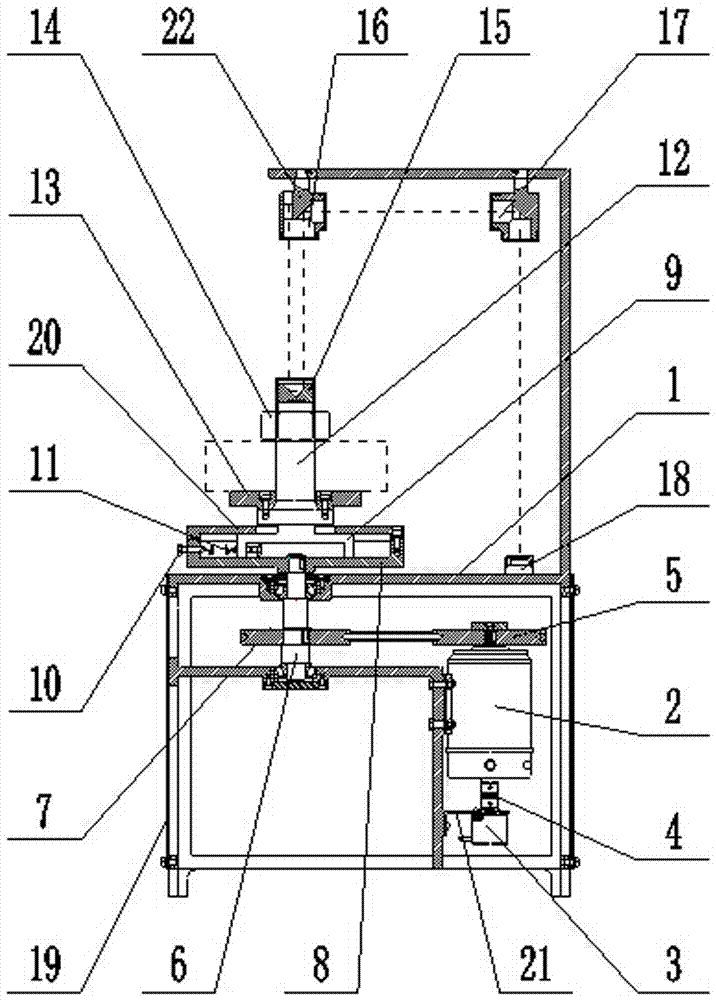
[0011] The optical dynamic balancing machine includes a frame 1. The side wall of the frame 1 is provided with a vertically arranged DC motor 2. A photoelectric rotary encoder 3 connected to the frame 1 is provided below the DC motor 2. The photoelectric rotary encoder 3 An elastic coupling 4 connected with the DC motor 2 is arranged, a driving wheel 5 is arranged above the DC motor 2, a rotating shaft 6 is arranged on the frame 1, and a driven wheel 7 is arranged on the rotating shaft 6, The driven wheel 7 and the driving wheel 5 are driven by a belt, and the upper end of the rotating shaft 6 is connected with a hollow flange 8 located above the frame 1, and the hollow flange 8 is sleeved with an inverted hollow flange I9. I9 and the hollow flange 8 are all screwed with some pairs of holed bolts 10 evenly arranged with both centers as the center of a circle, and each pair of holed bolts 10 is provided with an extension spring 11 connected to both, The upper end of the hollow ...


PUM


Abstract

The invention relates to an optical dynamic balance. Problems of low detection efficiency, easy damage and high manufacturing price of a current dynamic balancer can be solved. A direct-current motor is arranged on the side wall of a rack. An optical rotary encoder is arranged under the direct-current motor. A driving wheel and a driven wheel arranged on a rotation shaft are arranged on the direct-current motor. The upper end of the rotation shaft is connected with a hollow flange disc arranged on the rack. A hollow flange disc I is sleeved by the hollow flange disc. Hole-carrying bolts are screwed on the hollow flange disc I and the hollow flange disc. A stretching spring is arranged between the hole-carrying bolts. The upper end of the hollow flange disc is connected with a swinging shaft. The lower part of the swinging shaft is connected with a workpiece tray. A workpiece tray compressing screw is screwed on the upper part of the swinging shaft. A rectangular prism is arranged on the upper end of the swinging shaft. A rectangular prism I and a rectangular prism II are arranged on the rectangular prism. A laser emitter is arranged on one side of the rectangular prism I. A CCD module is arranged on the rack. In this way, precision is improved.

Description

technical field [0001] The invention relates to machine tools for mechanical engineering, in particular to an optical dynamic balancing machine capable of measuring and correcting the unbalanced amount of disc-type rotating parts. Background technique [0002] Commonly used machinery contains a large number of parts for rotating motion, such as various transmission shafts, main shafts, motors and rotors of steam turbines, etc., collectively referred to as rotary bodies. Ideally, when the revolving body is rotating and not rotating, the pressure on the bearing is the same, and such a revolving body is a balanced revolving body. However, due to various factors such as uneven material or blank defects, errors in processing and assembly, and even asymmetrical geometric shapes in design, the various rotating bodies in the project make the rotating body rotate. The centrifugal inertial force generated by each tiny particle cannot cancel each other out. The centrifugal inertial fo...

Claims


Application Information

Patent Timeline
Patent Type & Authority Patents(China)
IPC IPC(8): G01M1/16
CPCG01M1/16
Inventor 梁国星李光宋金鹏吕明
Owner TAIYUAN UNIV OF TECH
Features
  • R&D
  • Intellectual Property
  • Life Sciences
  • Materials
  • Tech Scout
  • Unparalleled Data Quality
  • Higher Quality Content
  • 60% Fewer Hallucinations
Learn More