Liquid crystal lens array and stereoscopic display apparatus

A technology of liquid crystal lens array and stereoscopic display device, which is applied in stereoscopic systems, optics, instruments, etc., can solve the problems of discontinuous viewing angle, easy to cause dizziness, inability to see 3D images, etc. Large adjustment range to meet user needs

Active Publication Date: 2016-05-11
洪煦 +1
View PDF7 Cites 19 Cited by
  • Summary
  • Abstract
  • Description
  • Claims
  • Application Information

AI Technical Summary

Problems solved by technology

However, we can imagine that the 3D display obtained by this kind of liquid crystal column lens with a strip structure is directional, and the viewer can only watch the 3D effect from certain specific directions; in addition, the viewing angle is discontinuous , there will be a shear zone in the middle, if the viewer happens to be in the shear zone, not only can’t see the tangential 3D image, but also easily cause dizziness and other discomfort symptoms

Method used


Image

  • Liquid crystal lens array and stereoscopic display apparatus
  • Liquid crystal lens array and stereoscopic display apparatus
  • Liquid crystal lens array and stereoscopic display apparatus

Examples


Embodiment 1

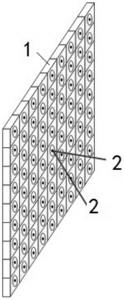
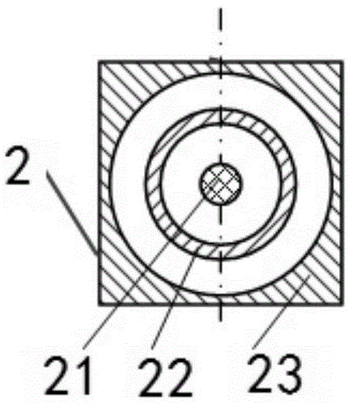
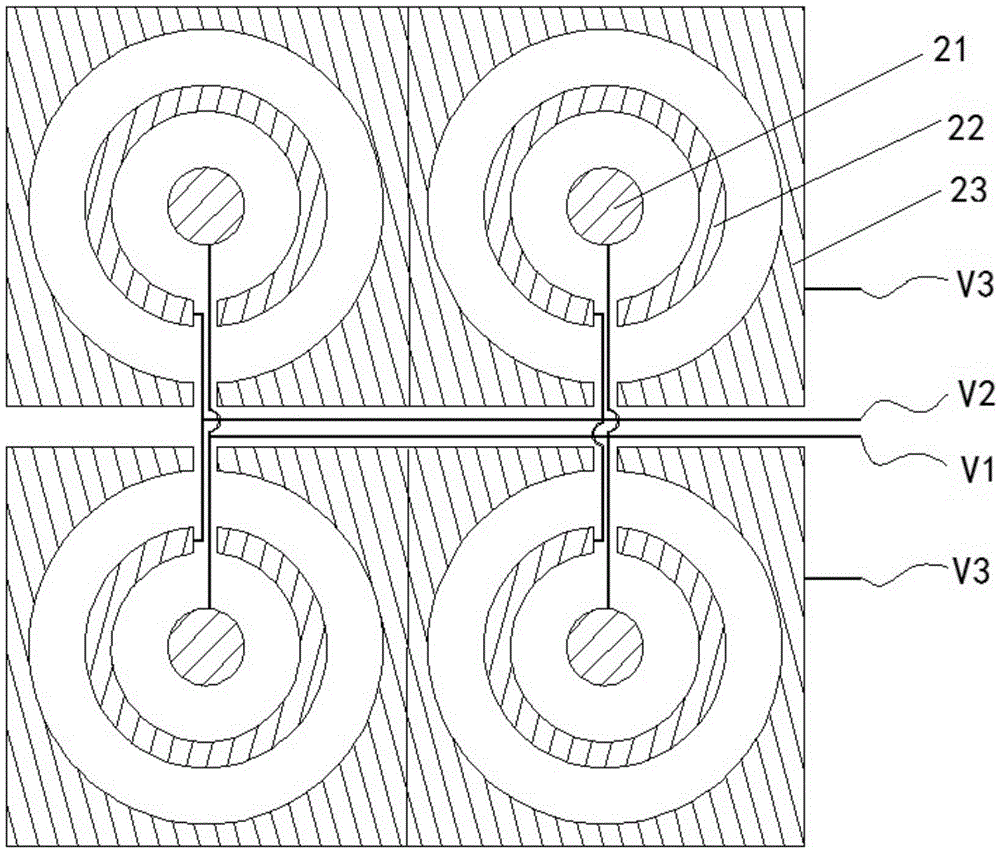
[0029] figure 1 It is a structural schematic diagram of the liquid crystal lens array 1 of the present embodiment; figure 2 yes figure 1 The structural representation of single liquid crystal microlens unit 2 in the shown liquid crystal lens array 1, will refer to below figure 1 , figure 2 The structure of the liquid crystal lens array 1 will be described. image 3 It is a structural schematic diagram of a liquid crystal lens array composed of 2×2 liquid crystal microlens units in an embodiment of the present invention. Figure 4 It is a schematic diagram of arrangement of liquid crystal molecules in any two adjacent liquid crystal microlens units in a liquid crystal microlens array according to an embodiment of the present invention in a power-on state.

[0030] Such as figure 1 As shown, this embodiment can also refer to Figure 2 to Figure 4 A liquid crystal lens array 1 described in this embodiment includes a plurality of liquid crystal microlens units 2, and each ...

Embodiment 2

[0040] This embodiment also provides a stereoscopic display device, including a display screen and a liquid crystal lens arranged on the display screen, and the liquid crystal lens adopts the liquid crystal lens array 1 as described in the first embodiment. The main structure of the liquid crystal lens array 1 is basically the same as that of the first embodiment, and will not be repeated here.

[0041] The liquid crystal microlens unit 2 forms a circular drop-shaped lens mirror surface after the first electrode and the second electrode 26 are energized.

[0042] Figure 4 It is a schematic diagram of the arrangement of liquid crystal molecules in any two adjacent liquid crystal microlens units 2 in the liquid crystal microlens array according to the present embodiment in a power-on state; Figure 5 It is a schematic diagram of the liquid crystal refractive index distribution curve of any two adjacent liquid crystal microlens units 2 in the power-on state in the liquid crysta...


PUM


Abstract

The invention provides a liquid crystal lens array and a stereoscopic display apparatus, and relates to the technical field of stereoscopic display. The liquid crystal lens array includes a plurality of liquid crystal microlens units, wherein each liquid crystal microlens unit includes a first glass substrate and a second glass substrate; the first glass substrate is plated with a first electrode; the second glass substrate is plated with a second electrode; liquid crystal is filled between the first glass substrate and the second glass substrate; and the first electrode includes a circular electrode at the center position, and at least two annular electrodes which are arranged in the shape of a concentric ring and take the circular electrode as the center. As the 3D display effect formed by the liquid crystal lens array has no directionality, a user can watch the required 3D effect from a wider angle, and the watching angle is more continuous, so that the 3D display effect of a stereoscopic display apparatus using the liquid crystal lens array becomes better and has no shear zones and the problem that the watcher becomes giddy because of being in the shear zone is effectively avoided.

Description

technical field [0001] The invention relates to the technical field of stereoscopic display, in particular to a liquid crystal lens array and a stereoscopic display device. Background technique [0002] The display industry has gone through many stages. With people's continuous pursuit of display effects, display technology has continued to improve, from static to dynamic, from black and white to color, from small size to large size, from bulky CRT to flat panel display; Display is facing the strong impact of stereoscopic (hereinafter referred to as 3D) display. Glasses-free 3D display technology and wearable 3D technology have both developed rapidly. Compared with wearable 3D technology, glasses-free 3D technology has the huge advantage of not needing to wear various auxiliary equipment, and the viewer is more free. [0003] At present, there are three-dimensional display devices that use liquid crystal lenses to realize naked-eye 3D display, which mainly utilizes positive...

Claims


Application Information

Patent Timeline
Patent Type & Authority Applications(China)
IPC IPC(8): G02B27/22G02F1/1343G02F1/29H04N13/04
CPCG02B30/27G02F1/134309G02F1/29H04N13/305
Inventor 洪煦虞晶怡
Owner 洪煦
Why Eureka
Try Eureka