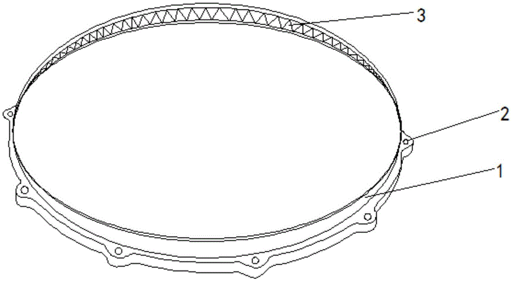
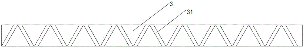
Anti-slippage drum ring structure
A technology to prevent slippage and drum loops, used in percussion instruments, instruments, musical instruments, etc., can solve the problems of drum skin falling off and affecting sound quality, and achieve the effect of increasing service life, preventing falling off, and facilitating replacement.
- Summary
- Abstract
- Description
- Claims
- Application Information
AI Technical Summary
Problems solved by technology
Method used
Image

Examples
Embodiment Construction
[0014] It should be noted that, in the case of no conflict, the embodiments of the present invention and the features in the embodiments can be combined with each other.
[0015] In describing the present invention, it should be understood that the terms "center", "longitudinal", "transverse", "upper", "lower", "front", "rear", "left", "right", The orientations or positional relationships indicated by "vertical", "horizontal", "top", "bottom", "inner", "outer", etc. are based on the orientation or positional relationships shown in the drawings, and are only for the convenience of describing the present invention Creation and simplification of description, rather than indicating or implying that the device or element referred to must have a specific orientation, be constructed and operate in a specific orientation, and therefore should not be construed as limiting the invention. In addition, the terms "first", "second", etc. are used for descriptive purposes only, and should no...
PUM
| Property | Measurement | Unit |
|---|---|---|
| Height | aaaaa | aaaaa |
Abstract
Description
Claims
Application Information
PatSnap Eureka turns technology decisions into work you can execute. Powered by our Innovation Knowledge Graph, it runs expert workflows across engineering, life sciences, materials and intellectual property. Get your review-ready output in minutes.


