

Catheter having deflectable leading end
A catheter and hose technology, which is applied in the field of catheters whose front end can be operated in a biased direction, can solve the problems of reduced adhesion, poor wettability, and the front end chip electrode falling off in the living body, and achieves the effect of preventing falling off and preventing prolapse
- Summary
- Abstract
- Description
- Claims
- Application Information
AI Technical Summary
Problems solved by technology
Method used
Image

Examples
no. 1 Embodiment approach
[0057] Hereinafter, the present invention will be described based on the embodiments shown in the drawings.
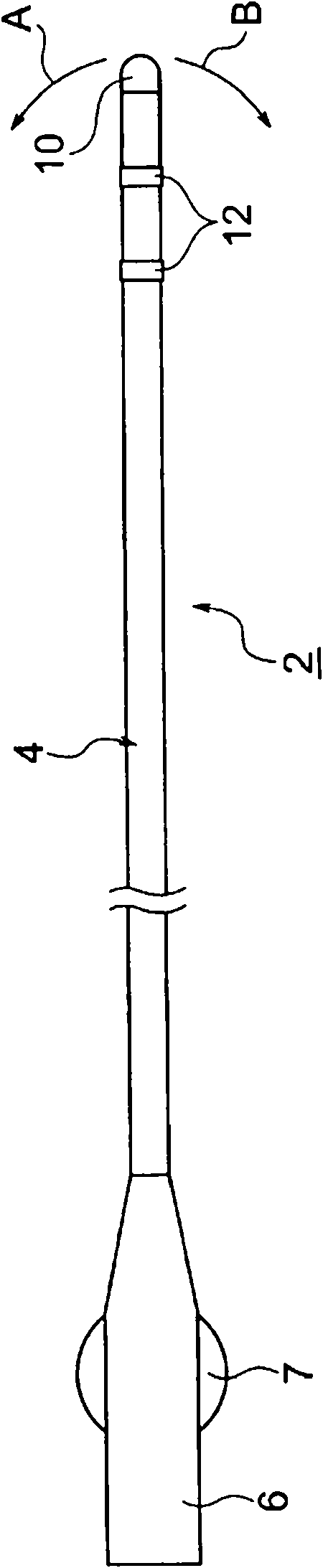
[0058] figure 1 The lead catheter 2 of the illustrated embodiment is used, for example, for the diagnosis or treatment of cardiac arrhythmias.
[0059] exist figure 1 Among them, the reference numeral 4 is a hose, the reference numeral 10 is a front-end chip electrode fixed at the distal end of the hose 4, and the reference numeral 12 is a ring-shaped electrode installed at the distal end of the hose 4. Reference numeral 6 is a connector (handle) mounted on the proximal end of the hose 4, and reference numeral 7 is a roller mounted on the connector 6 for performing a biased movement operation (swing operation) of the distal end of the hose 4 . Wires (not shown) electrically connected to the front-end chip electrode 10 and the ring electrode 12 are led out from the connector 6 .
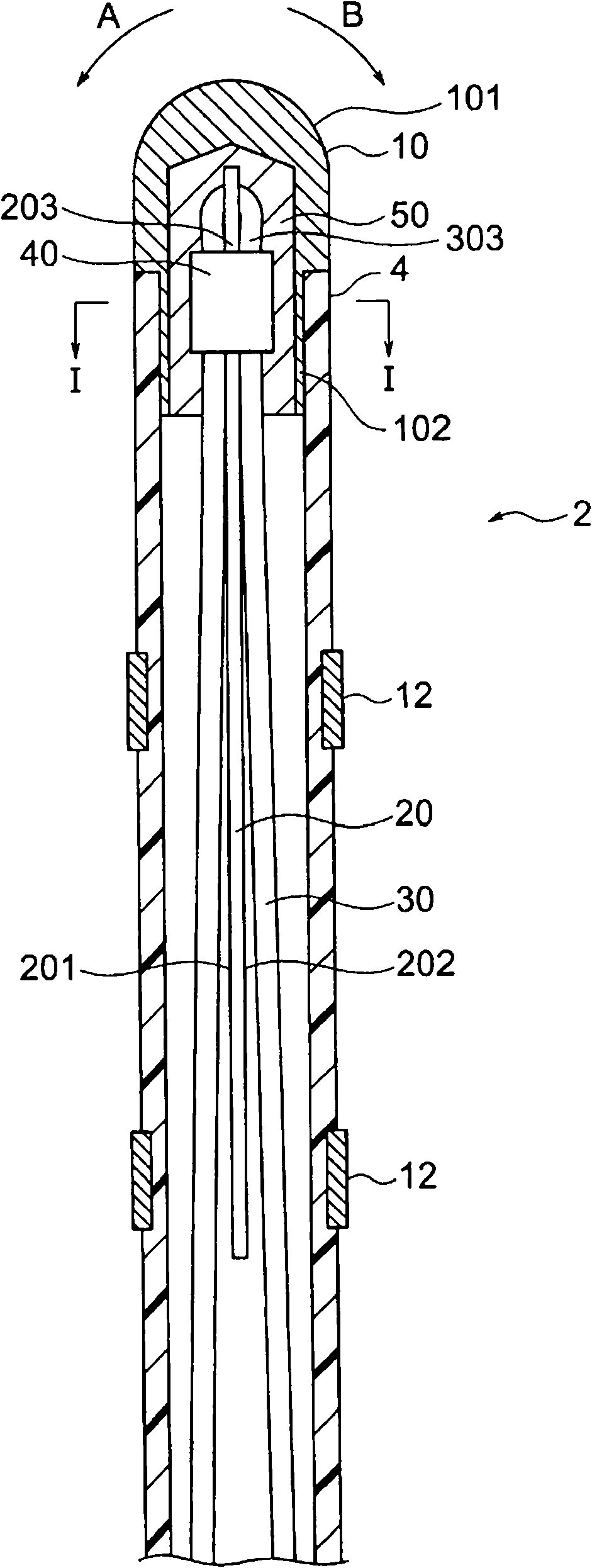
[0060] Such as Figure 2 ~ Figure 4 As shown, the electrode catheter 2 of this embo...
no. 2 Embodiment approach
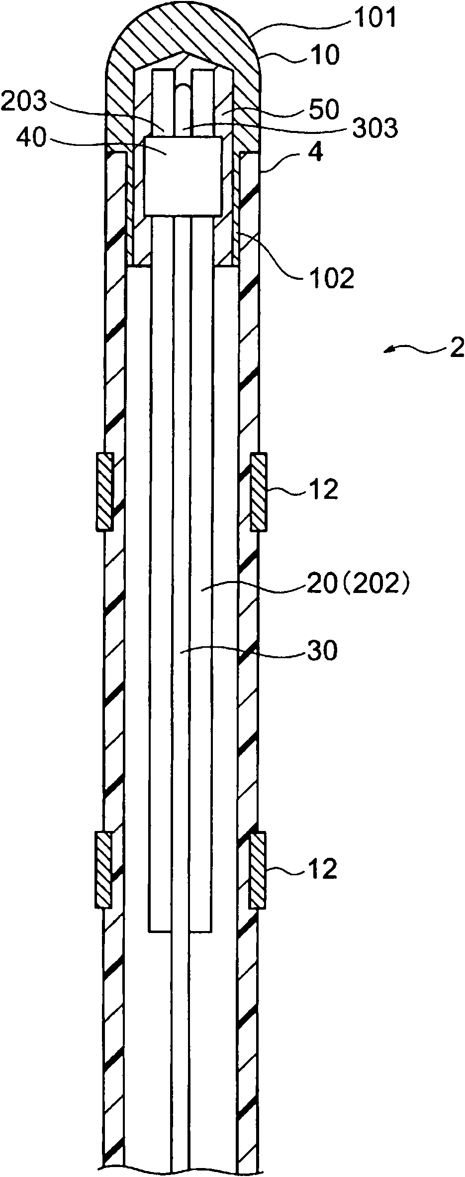
[0095] Figure 6 and Figure 7 It is a partially cutaway front view and a partially cutaway plan view of the distal end side of an electrode catheter according to another embodiment of the present invention.
[0096] In addition, the same reference numerals are used for the same or corresponding components as those of the first embodiment.
[0097] The appearance shape of the electrode catheter of this embodiment and figure 1 The first embodiment shown is the same. Such as Figure 6 and Figure 7 As shown, the electrode catheter of this embodiment includes: a flexible tube 4; a front chip electrode 10 fixed at the distal end of the flexible tube 4; a plurality (two) ring-shaped electrodes 12 installed at the distal end of the flexible tube 4 ; the leaf spring 25 disposed inside the distal end side (near the distal end) of the hose 4 ; the operation wire 35 arranged to extend axially inside the hose 4 ; The distal end is clamped and fixed to the ring member 40 on the sur...
no. 3 Embodiment approach
[0117] Figure 8 and Figure 9 It is a partially cutaway front view and a partially cutaway plan view of the distal end side of the electrode catheter according to still another embodiment of the present invention.
[0118] In addition, the same code|symbol is attached|subjected to the component which is the same as or corresponds to 2nd Embodiment.
[0119] The appearance shape of the electrode catheter of this embodiment and figure 1 The first embodiment shown is the same. Such as Figure 8 and Figure 9 As shown, the electrode catheter of this embodiment has the same structure as that of the second embodiment, and further includes: an operation wire 36 arranged to extend along the surface 251 of the leaf spring 25 inside the hose 4; The anti-dropping sleeve 61 at the distal end of the wire 36.
[0120] The manipulation wire 36 constituting the electrode catheter of the present embodiment is a wire whose one end is a proximal end, and is directed toward the distal dir...
PUM
 Abstract
Description
Claims
Application Information