Friction stir welding method for steel sheets and method of manufacturing joint

A joining method, friction stir technology, applied in manufacturing tools, welding/welding/cutting items, welding equipment, etc., can solve problems such as temperature rise

Active Publication Date: 2016-05-11
JFE STEEL CORP
View PDF13 Cites 12 Cited by
  • Summary
  • Abstract
  • Description
  • Claims
  • Application Information

AI Technical Summary

Problems solved by technology

As a result, only the vicinity of the probe 62 is heated in the unjoined portion 13, thereby increasing the temperature of the vicinity of the probe and its surrounding area.

Method used


Image

  • Friction stir welding method for steel sheets and method of manufacturing joint
  • Friction stir welding method for steel sheets and method of manufacturing joint
  • Friction stir welding method for steel sheets and method of manufacturing joint

Examples


Embodiment 1

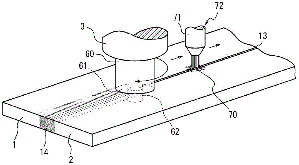
[0097] Figure 4 The friction stir welding apparatus used for practice of this invention is shown. In this device, the induction heating device 4 is arranged in front of the bonding tool 60 in the traveling direction, and the induction heating device 8 is arranged behind it, so that heating can be performed by these induction heating devices. The tool 60 has a shape having a protruding probe 62 made of tungsten carbide as a base material and a flat shoulder 61 . In addition, in order to suppress oxidation of the joint portion, the joint was performed while blowing argon gas from the front in the traveling direction of the tool 60 .

[0098] It should be noted that among the figures, symbol 9 is a cooling device, 35 is a power supply, and 40 is a heating temperature setting panel.

[0099] use Figure 4 The friction stir welding apparatus shown in , performs friction stir welding under the conditions shown in Table 1 on a steel plate (C: 0.3% by mass, Si: 0.1% by mass, Mn: 1...

Embodiment 2

[0106] Same as Example 1, use Figure 4 The friction stir welding apparatus shown in , performed friction stir welding under the conditions shown in Table 2. The joining conditions were almost the same as in the case of Example 1, but in this example, a liner material was used at the time of joining.

[0107] Table 2 shows the results of investigations on the availability of welding, joint efficiency, and stability of weld bead width when the above-mentioned friction stir welding was carried out. Regarding the bead width, the minimum bead width and the maximum bead width were measured, and it was stable if the difference was 20% or less of the minimum bead width.

[0108]

[0109] As shown in Table 2, when performing friction stir welding based on the present invention, even at a welding speed exceeding 0.5 m / min, a stable weld width can be obtained without welding defects and at high joint efficiency. Engagement joints.

Embodiment 3

[0111] Same as Example 1, use Figure 4 In the friction stir welding apparatus shown in , friction stir welding was performed under the conditions shown in Table 3. The bonding conditions are almost the same as those in the first embodiment, but in this third embodiment, the cooling device 9 and the rear heating device 8 are used to carry out the bonding.

[0112] Table 3 shows the joint efficiency of the above-mentioned friction stir welding and the standard deviation of the joint efficiency of 10 samples obtained under the same conditions.

[0113] Regarding the possibility of joining, ○ and ◎ indicate that it can be joined, and the ◎ mark indicates that the tool can be joined without damage, and there is no visible defect in the entire length of the joint and the weld width is stable; the ○ mark indicates that the tool can be joined without damage and the joint part There is no visible defect; the X mark indicates that the tool is damaged or there is a visible defect in th...


PUM


Abstract

A friction stir welding method for joining steel sheets to one another, wherein a heating device (4) positioned to the front in the direction of travel of a rotating tool pre-heats a section to be joined prior to joining thereof by the rotating tool (10), and when doing so, the surface temperature distribution in the direction perpendicular to the direction of travel at the position at which the joining by the rotating tool (10) starts is set in a manner such that given that TAc1 serves as the Ac1 point of a steel sheet, then the maximum temperature (TU) is in the range of 0.6*TAc1<TU<1.8*TAc1, and given that L is the width of the heating region above temperature (TL)=0.6*TAc1, then the relationship 0.3*d<=L<=2.0*d is satisfied for the shoulder section diameter (d). As a result, it is possible to improve joint strength while operating at a high joining speed, without any risk of joining failures or joining-tool breakage, and without any risk of temper softening or embrittlement from curing in the heat-affected areas.

Description

technical field [0001] The present invention relates to a friction stir welding method of steel plates, and in particular to a friction stir welding method of steel plates for improving joint strength. Background technique [0002] The Friction Stir Welding method is a method in which a rotary tool is inserted into an unjoined portion of overlapping or butted workpieces and moved while rotating, and the workpiece is softened by frictional heat from the rotary tool and the rotary tool is used The plastic flow created by stirring the softened portion enables joining without the addition of filler metal. [0003] In this specification, for example, the butted portion where the steel plates are only butted but not yet joined is referred to as “unjoined portion”, while the portion integrated by plastic flow joining is referred to as “joined portion”. [0004] figure 1 An example of friction stir welding of butt steel plates is shown. [0005] Such as figure 1 As shown, in thi...

Claims


Application Information

Patent Timeline
Patent Type & Authority Applications(China)
IPC IPC(8): B23K20/12
CPCB23K20/122B23K20/1235B23K20/227B23K2101/18B23K2103/04C21D1/42C21D9/50C21D9/505Y02P10/25B23K20/1205B23K20/1225
Inventor 谷口公一松下宗生池田伦正
Owner JFE STEEL CORP
Why Eureka
Try Eureka