Method and device for applying forces and motions to warp threads of weaving machine

A movement and loom technology, applied in looms, textiles, textiles and papermaking, etc., can solve problems such as low warp tension

Inactive Publication Date: 2016-05-11
LINDAUER DORNIER GMBH
View PDF15 Cites 2 Cited by
  • Summary
  • Abstract
  • Description
  • Claims
  • Application Information

AI Technical Summary

Problems solved by technology

However, as implemented above, this ...

Method used


Image

  • Method and device for applying forces and motions to warp threads of weaving machine
  • Method and device for applying forces and motions to warp threads of weaving machine
  • Method and device for applying forces and motions to warp threads of weaving machine

Examples


Embodiment Construction

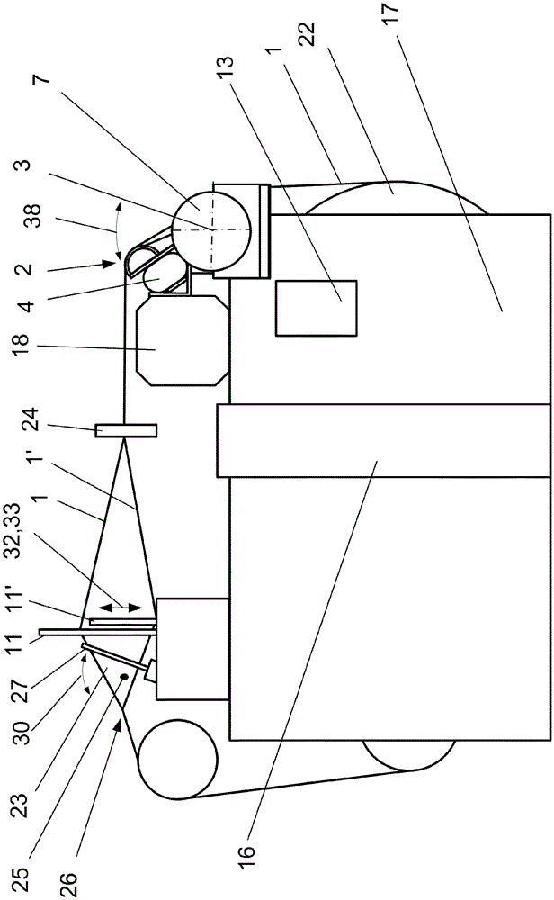
[0069] figure 1 shows a side view of a weaving machine with an embodiment of the device according to the invention; figure 2 An excerpt of it is shown.

[0070] On the rear side of the loom, the loom has a warp beam 22 from which the warp threads 1 are drawn. The warp threads 1 are supplied to the thread deflecting elements 2 in the present example via deflecting tubes 28 . The warp yarn 1 is deflected from the drawing direction to the weaving plane by means of the yarn deflecting element 2 . In order to monitor the warp thread 1, a warp thread monitor 24 is provided in the present example, which limits the vertical movement of the warp thread in the rear shed (ie between the shed former 11 and the warp beam 22), but does not impede Horizontal movement of the warp.

[0071] In the weaving plane, the warp threads 1 , 1 ′ are guided via the shed formers 11 , 11 ′ and the reed 27 into the front region of the weaving machine. The warp threads 1 , 1 ′ run vertically through t...


PUM


Abstract

The invention relates to a method for applying forces and motions to warp threads (1, 1 ') of a weaving machine, comprising the following steps: deflecting the warp threads (1, 1 ') via a thread-deflecting element (2), which is supported in such a way that the thread-deflecting element can be pivoted about a pivot axis (3); applying spring forces to the thread-deflecting element (2) by means of more than three force application points (5) along a first line (6), which extends parallel to the pivot axis (3), wherein the spring forces are applied by at least one spring element (4); applying a specified forced-oscillation motion (38) to the thread-deflecting element (2), wherein said motion (38) is applied by a drive means (7) via a drive element (8), wherein the forces on the thread-deflecting element (2) are supported partially on at least one spring element (4) by means of the thread-deflecting element (2) and partially on the drive means (7) by means of the drive element (8). The invention further relates to a corresponding device.

Description

technical field [0001] The present invention relates to methods and devices for imparting force and motion to warp threads of a loom. Background technique [0002] For weaving machines, devices are known in the prior art with which forces and movements can be exerted on the warp threads of the weaving machine. [0003] Such a device is shown, for example, in DE 2731046 A1, which document is considered the closest prior art. This document relates to a method for balancing warp tension at a weaving machine with a movably supported self-stabilizing continuous oscillating backrest, characterized in that the oscillating backrest consists of at least one pressure pad extending substantially in the longitudinal direction of the oscillating backrest block support. [0004] WO1997030201A1 shows a tensioning device for a warp thread sheet, in which a tensioning roller is provided, which is elastically and retractably supported several times over its length by means of support roller...

Claims


Application Information

Patent Timeline
IPC IPC(8): D03D49/14D03D49/22
CPCD03D49/14D03D49/22D03D49/06
Inventor M.吉伦
Owner LINDAUER DORNIER GMBH
Why Eureka
Try Eureka