
Core inserting machine and core inserting method

A core inserting machine and core tube technology, applied in metal processing, metal processing equipment, manufacturing tools, etc., can solve the problems of large core inserting efficiency, tapered core tube inserting position error, etc., to improve core inserting efficiency and cost The effect of low and stable conveying speed

Active Publication Date: 2017-10-31
浙江三友塑业股份有限公司
View PDF6 Cites 0 Cited by
  • Summary
  • Abstract
  • Description
  • Claims
  • Application Information

AI Technical Summary

Problems solved by technology

[0003] The purpose of the present invention is to overcome the disadvantages that the current tapered core tube is mounted on the small end of the tapered hole. The tapered core tube is usually installed manually, and there is a large error in the position of the tapered core tube and the low efficiency of the core. Provided are a core-inserting machine and a core-inserting method with a small error in the mounting position of a tapered core tube and high core-inserting efficiency

Method used


Image

  • Core inserting machine and core inserting method
  • Core inserting machine and core inserting method
  • Core inserting machine and core inserting method

Examples


Embodiment Construction

[0024] The present invention will be further described below in conjunction with the accompanying drawings.

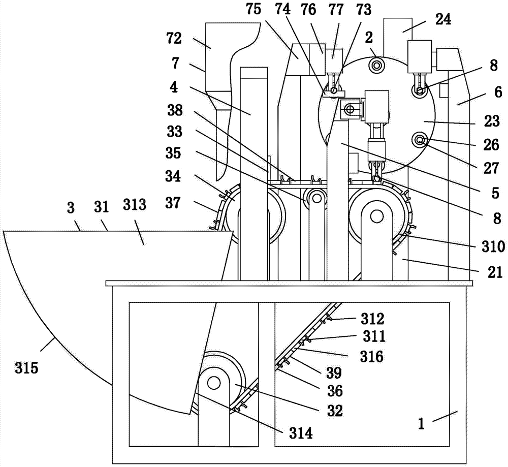
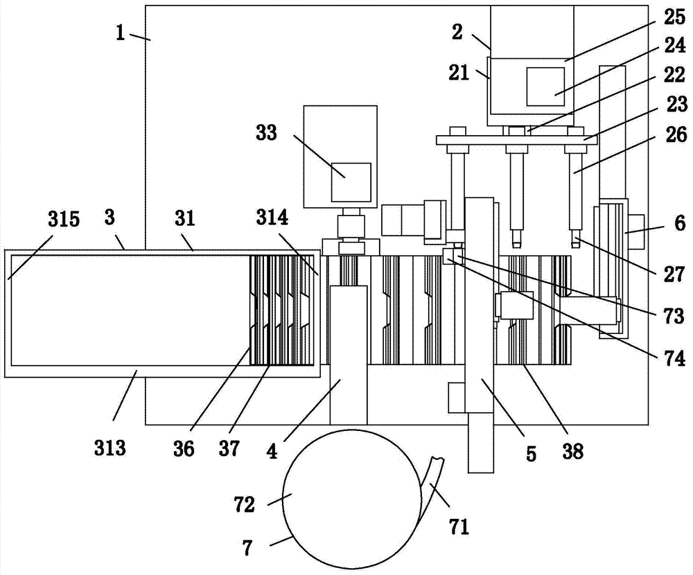
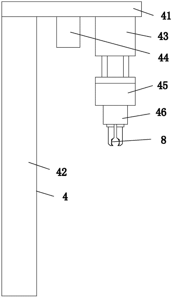
[0025] as attached figure 1 To attach Figure 7 Shown: a core inserting machine, including a frame 1, an indexing mounting device 2 connected to the frame 1, a tapered outer tube delivery device 3 located in front of the indexing mounting device 2, and a tapered outer tube orientation Manipulator 4, manipulator 5 for conical outer tube entry, bobbin exit manipulator 6, tapered core tube directional entry device 7.

[0026] In this embodiment, the transposition mounting device 2 includes: a mounting bracket 21 screwed to the frame 1, and a turntable 23 of a transverse shaft 22 pivotally connected to the mounting bracket 21 through a bearing at the rear end. There is a transmission 25 with a turntable drive motor 24, six inlaid shafts 26 uniformly distributed along the rotation axis of the transverse shaft 22 and the rear end is threadedly connected to the front end of...


PUM


Abstract

The invention relates to the field of textiles and aims at providing core insertion machine and method. The core insertion machine comprises a rack, a transposition inserting device which is connected with the rack, a conical outer tube conveying device arranged on the front side of the transposition inserting device, a conical outer tube directional manipulator, a conical outer tube locating manipulator, a bobbin dislocation manipulator and a conical core tube directional locating device. The core insertion machine ensures an error of the conical core tube insertion position to be small and the core insertion efficiency to be higher. The core insertion method of the core insertion machine can meet the requirements for core insertion and is smaller in error of the conical core tube insertion position and higher in the core insertion efficiency.

Description

technical field [0001] The invention relates to the textile field, in particular to a core inserting machine and a core inserting method. Background technique [0002] Yarn tubes are commonly used in the textile industry; yarn tubes include a tapered outer tube with a tapered hole and a tapered core tube mounted on the small end of the tapered hole; the tapered core tube is mounted on the small end of the tapered hole. It is done by hand, and there is a large error in the mounting position of the tapered core tube and a low core mounting efficiency. Therefore, a core mounting machine with a small error in the mounting position of the tapered core tube and high core mounting efficiency is designed. The core setting method has become an urgent problem to be solved. Contents of the invention [0003] The purpose of the present invention is to overcome the disadvantages that the current tapered core tube is mounted on the small end of the tapered hole. The tapered core tube i...

Claims


Application Information

Patent Timeline
Patent Type & Authority Patents(China)
IPC IPC(8): B23P19/027
CPCB23P19/027
Inventor 戴云卿秦春华王慧卿梁道聪
Owner 浙江三友塑业股份有限公司
Learn More