
Turbine rotor roller bracket

A steam turbine rotor and roller support technology, applied in the direction of workbench, manufacturing tools, etc., can solve the problems of rotor damage, non-conformity of contact line between nylon roller and rotor journal, fluffing of rotor journal, etc., and achieve the elimination of stress concentration phenomenon Effect

Active Publication Date: 2017-09-22
SHANGHAI HAIYE ELECTROMECHANICAL EQUIP CO LTD
View PDF8 Cites 0 Cited by
  • Summary
  • Abstract
  • Description
  • Claims
  • Application Information

AI Technical Summary

Problems solved by technology

However, after using the roller bracket, another problem occurred: the contact line between the outer peripheral surface of the nylon roller and the outer peripheral surface of the rotor journal cannot be well matched, that is, the nylon roller and the rotor journal change from line contact to point contact, resulting in serious problems. The stress concentration of the nylon roller will not only damage the nylon roller, but also very likely to fluff the rotor journal.
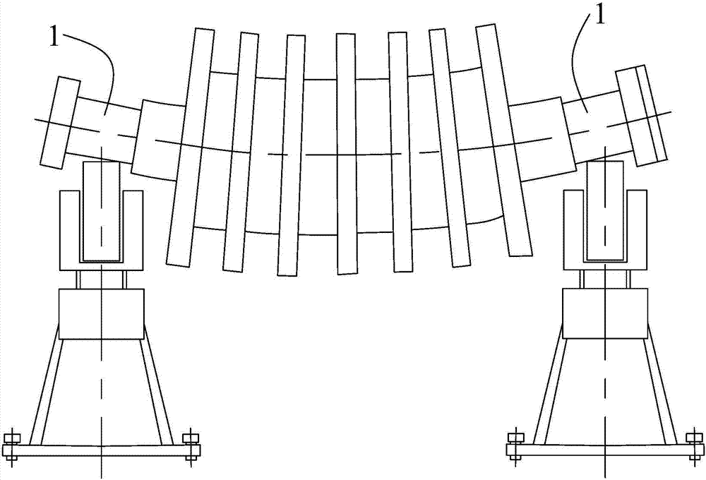
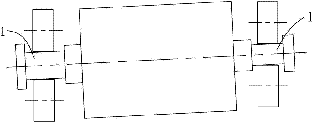
[0005] Further, as figure 1 As shown, no matter how thick the rotor is, it also has deflection, so the middle part of the rotor sinks. The two roller brackets placed at the rotor journals at the front and rear ends of the rotor are placed evenly, and the contact line between the nylon roller and the rotor journal is also flat. do not match; in addition, if figure 2 As shown in the figure, after the two roller brackets are placed on the ground five or six meters apart, the two roller brackets cannot be completely in a straight line, which will also cause the nylon rollers to not fit well with the rotor journal.
For a rotor of more than 100 tons, manpower cannot adjust it slightly, and the left and right direction is wrong after the up and down adjustment, or the front and rear direction is wrong after the left and right adjustment. Therefore, during the contact process between the nylon roller and the rotor journal, There will always be a phenomenon of stress concentration, and as long as the momentary large stress concentration has occurred, the rotor will be damaged

Method used


Image

  • Turbine rotor roller bracket
  • Turbine rotor roller bracket
  • Turbine rotor roller bracket

Examples


Embodiment Construction

[0060] The implementation of the present invention will be illustrated by specific specific examples below, and those skilled in the art can easily understand other advantages and effects of the present invention from the contents disclosed in this specification.

[0061]It should be noted that the structures, proportions, sizes, etc. shown in the drawings attached to this specification are only used to match the content disclosed in the specification, for those who are familiar with this technology to understand and read, and are not used to limit the implementation of the present invention. Limiting conditions, so there is no technical substantive meaning, any modification of structure, change of proportional relationship or adjustment of size, without affecting the effect and purpose of the present invention, should still fall within the scope of the present invention. The disclosed technical content must be within the scope covered. At the same time, terms such as "upper",...


PUM


Abstract

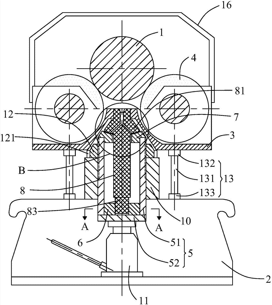
The invention provides a novel roller bracket for a steam turbine rotor. The novel roller bracket comprises a base, a roller bracket body located above the base, and two supporting rollers arranged in a left-right symmetry mode. The two supporting rollers are both mounted in the roller bracket body in a rotatable mode. After the rotor is placed on the novel roller bracket for the steam turbine rotor, the two supporting rollers are located on the left side and the right side of a rotor journal respectively, and the outer circumferential faces of the supporting rollers make contact with the outer circumferential face of the rotor journal. The supporting rollers can rotate along the vertical radial line of the rotor journal, and swing front and back along the transverse radial line of the rotor journal. After the rotor is placed on two novel roller brackets, oppositely arranged front and back, for the steam turbine rotor, the supporting rollers can rotate and swing front and back automatically through pressure of the rotor on the supporting rollers, so that the outer circumferential faces of the supporting rollers are always in line contact with the outer circumferential face of the rotor journal, point contact between the supporting rollers and the rotor journal is avoided, and therefore the phenomenon of stress concentration is avoided, and burring of the outer circumferential face of the rotor journal and damage to the rotor are prevented.

Description

technical field [0001] The invention relates to the field of steam turbines and auxiliary tooling for steam turbine parts, in particular to a steam turbine rotor roller bracket. Background technique [0002] A steam turbine is a rotary power machine that converts the energy of steam into mechanical work, also known as a steam turbine. It is the most widely used prime mover in modern thermal power plants. It has the advantages of high single-machine power, high efficiency, and long life. The steam turbine is mainly composed of two aspects: a rotating part and a stationary part. The rotating part includes rotors, impellers, moving blades, couplings, etc., and the stationary part includes cylinders, baffles, static cascades, steam seals, bearings, etc. At present, the rotors used for large steam turbines and generators weigh up to 100 tons, and the maximum can reach 300 tons; After years of continuous operation, these units have gradually entered the period of overhaul, in whi...

Claims


Application Information

Patent Timeline
Patent Type & Authority Patents(China)
IPC IPC(8): B25H1/06
CPCB25H1/06
Inventor 鲍勇李震洪权正钟
Owner SHANGHAI HAIYE ELECTROMECHANICAL EQUIP CO LTD
Learn More