Simulated mechanical finger pulled on basis of steel wire

A mechanical finger and mechanical finger technology, applied in the field of simulated mechanical fingers, can solve the problems of increased equipment weight, high cost, inaccurate positioning of mechanical fingers, etc., and achieve the effect of strong adaptability and simple structure for grasping objects

Active Publication Date: 2016-05-18
天津十元素金属制品有限公司
View PDF6 Cites 12 Cited by
  • Summary
  • Abstract
  • Description
  • Claims
  • Application Information

AI Technical Summary

Problems solved by technology

[0002] At present, the driving methods of the fingers of manipulators are mostly driven by servo motors, steel wires, hydraulic drives, etc., and a small part are driven by artificial muscles. Among them, artificial muscle drives, although the driving method is advanced, but the manufacturing cost is currently very high, and hydraulic drives require powerful The power to pressurize the hydraulic oil will increase the weight of the equipment and require higher technical maturity, so the cost is also higher; then, servo motor drive and wire drive are more common in the finger drive of the simulated manipulator, and the servo motor drive is Installing a servo motor on each joint will make the mechanism on the mechanical finger very unsightly. The size and shape of the servo motor will determine the shape and function of the mechanical finger; currently the most used and the lowest cost is the use of steel wire drive, The servo motors are centrally installed on the arm, the mechanism of the manipulator and fingers is relatively simple, and the control is relatively easy. However, in the steel wire drive, it is easy to cause inaccurate positioning of the mechanical designation and swinging of fingers.

Method used


Image

  • Simulated mechanical finger pulled on basis of steel wire
  • Simulated mechanical finger pulled on basis of steel wire
  • Simulated mechanical finger pulled on basis of steel wire

Examples


Embodiment Construction

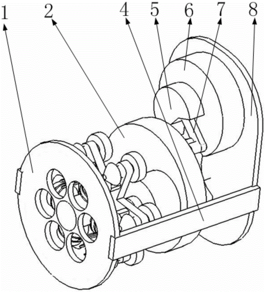
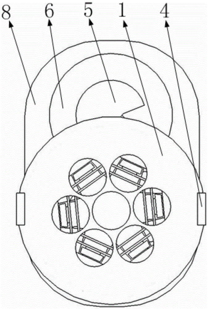
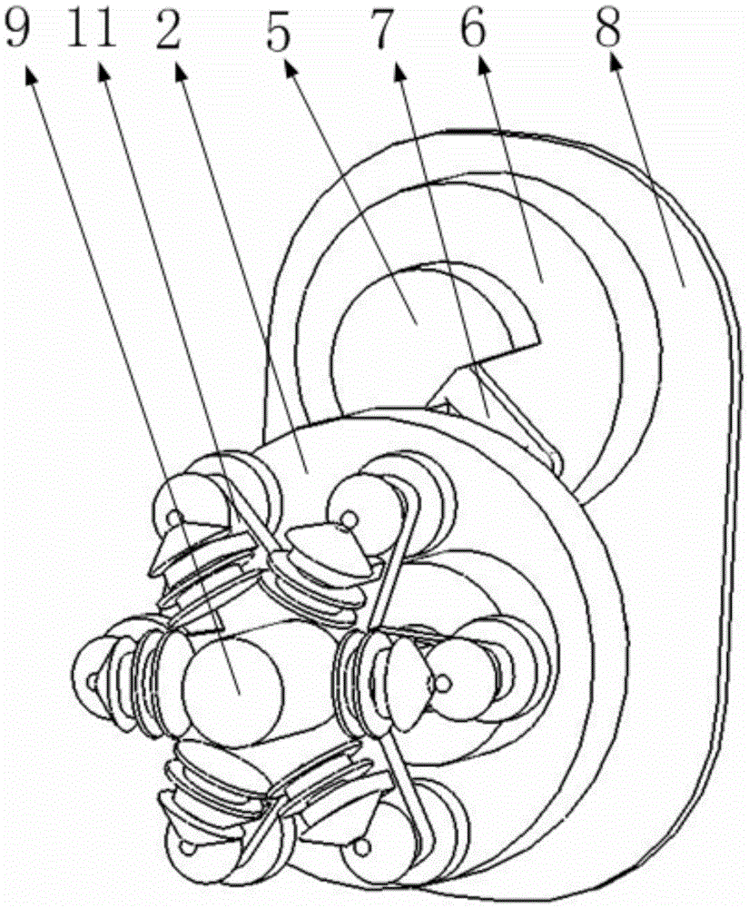
[0039] like Figure 15 , 16 As shown, it includes the fourth support of the mechanical finger, the third support of the mechanical finger, the steel wire guide plate, the steel wire, the second support of the mechanical finger, the first support of the mechanical finger, the wire hole of the first support of the mechanical finger, the tension spring of the mechanical finger support, the mechanical finger The second return spring, the third return spring of the mechanical finger, the fixing plate of the return spring, the wire guide groove, the pulling plate of the mechanical finger, the first return spring of the mechanical finger, and the limit plate of the mechanical finger bracket, wherein the second bracket of the mechanical finger is installed by a cylindrical pin On the first bracket of the mechanical finger, the third bracket of the mechanical finger is installed on the second bracket of the mechanical finger through the cylindrical pin, the fourth bracket of the mechan...


PUM


Abstract

The invention belongs to the technical field of mechanical finger driving, and particularly relates to a simulated mechanical finger pulled on the basis of a steel wire. The simulated mechanical finger comprises four mechanical finger supports, the steel wire, reset springs, tension springs and the like. The mechanical finger supports are connected together through cylindrical pins to form the mechanical finger. The original vertical state of the mechanical finger is guaranteed in the manner that the reset springs are arranged on the back faces of the bent sides of the supports. The parts, on the bent sides of the supports, of the steel wire and the supports are connected through the tension springs. Due to the fact that the elastic coefficients of the designed three reset springs are different, the bending resistances of knuckles of the mechanical finger are different, and the mechanical finger can show the bending degree the same as the bending degree of the finger of a person. In addition, each support is driven in a manner that the steel wire is pulled by the corresponding tension spring, and by means of the tension springs, it can be guaranteed that when the mechanical finger grabs an object, the bending degree of the knuckles of the mechanical finger can be changed according to the shape of the object. Each mechanical finger is driven through single power, and the beneficial effects that the object grabbing adaptability is high, and the structure is simple are achieved.

Description

Technical field [0001] The invention belongs to the technical field of mechanical finger driving, and in particular relates to a simulated mechanical finger based on wire pulling. Background technique [0002] At present, the driving methods of the fingers of the manipulator mostly use servo motor drive, wire drive, hydraulic drive, etc., and a few use artificial muscle drive; among them, artificial muscle drive, although the drive method is advanced, but the manufacturing cost is currently high, and hydraulic drive requires powerful Power to boost the hydraulic oil drive will increase the weight of the equipment and require higher technical maturity, so the cost is also higher; then the servo motor drive and wire drive are more common in the simulated manipulator finger drive, and the servo motor drive is A servo motor is installed on each joint, which will cause the mechanism on the robot finger to be unsightly. The size and shape of the servo motor will determine the shap...

Claims


Application Information

Patent Timeline
Patent Type & Authority Applications(China)
IPC IPC(8): B25J15/00B25J15/08F16H37/06F16H27/04F16H1/22
CPCB25J15/0009B25J15/08F16H1/222F16H27/04F16H37/065
Inventor 柳超
Owner 天津十元素金属制品有限公司
Why Eureka
Try Eureka