Temperature control safety explosion-proof lamp

An explosion-proof lamp and safety technology, which is applied to the safety device of the lighting device, the lighting device, the cooling/heating device of the lighting device, etc., can solve the problems of injuring the surrounding staff, heating the surface of the electrical equipment, hidden dangers of the explosion-proof lamp, etc. Achieve the effect of ingenious structure, simplified installation procedure, and solved production cost and production difficulty

Active Publication Date: 2018-07-31
沈阳北方防爆股份有限公司
View PDF12 Cites 0 Cited by
  • Summary
  • Abstract
  • Description
  • Claims
  • Application Information

AI Technical Summary

Problems solved by technology

[0002] Explosion-proof lamps refer to lamps that take various specific measures to prevent the ignition of surrounding explosive mixtures such as explosive gas atmospheres, explosive dust atmospheres, gas gases, etc.; it is widely used in oil mining, oil refining, chemical industry, coal mines, railways, flood control, Dangerous environments such as military industry and offshore oil platforms, oil tankers and other places; common explosion-proof lamps are divided into explosion-proof lamps, increased safety lamps, composite lamps, etc. according to the structural type; there are two reasons for the ignition of flammable gas mixtures by electrical equipment: One is the sparks and arcs generated by electrical equipment, and the other is the heating on the surface of electrical equipment; placing equipment that is prone to arcing inside the explosion-proof shell can effectively prevent explosions, but traditional explosion-proof lamps still generate high heat during operation. When the temperature reaches a critical value, it will still cause an explosion, so the traditional explosion-proof lamp still has a large safety hazard during use; in addition, the fragments emitted by some explosion-proof lamps when they explode and shatter will hurt the surrounding staff, and there are Greater personal safety hazard

Method used


Image

  • Temperature control safety explosion-proof lamp
  • Temperature control safety explosion-proof lamp

Examples


Embodiment

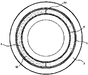
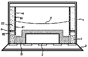
[0014] exist figure 1 , figure 2 In the shown embodiment, the temperature control safety explosion-proof lamp includes a housing 1, a lamp sheet 2 and a lampshade 3, and the lampshade 3 seals and fixes the lamp sheet 2 on the housing 1; The back of the sheet 2 is attached with a heat dissipation block 21 with good heat conduction; a cylindrical partition 4 is installed in the housing 1, and the upper and lower ring edges of the partition 4 are respectively airtightly connected to the top plate of the housing 1 and the back of the light sheet 2; the partition 4 is in close contact with the heat dissipation block 21; it is installed symmetrically in the airtight annular cavity 5 surrounded by the partition 4, the housing 1 and the light sheet 2 There are two sub-chamber plates 51, which divide the annular cavity 5 into two independent semi-annular liquid storage chambers 52; Annular piston sheet 6; coolant is filled above the piston sheet 6, and air and expansion glue 7 are f...


PUM


Abstract

The invention relates to a temperature control safety explosion-proof lamp. The temperature control safety explosion-proof lamp comprises a shell, a lamp piece and a lampshade. A good-heat-conduction heat dissipation block is attached to the back face of the lamp piece, annular cylindrical partition plates are mounted in the shell, and two cavity dividing plates are symmetrically mounted in a sealed annular cavity defined by the partition plates, the shell and the lamp piece; the annular cavity is divided into two independent semicircular liquid storage cavities through the cavity dividing plates, and horizontal semicircular piston pieces are mounted in the liquid storage cavities; the positions above the piston pieces are filled with a cooling agent, and the positions below the piston pieces are filled with air and expansion glue; and cooling holes communicated with the cooling agent are formed in the upper portions of the partition plates, and air inlet holes are formed in the lower portions of the partition plates. According to the explosion-proof lamp, the temperature inside a lamp body can be effectively reduced, safe and stable running of the explosion-proof lamp can be ensured, meanwhile, the explosion-proof lamp has the shutoff protection function, and the phenomenon that after the lamp body is exploded, electric sparks are still generated is effectively avoided.

Description

technical field [0001] The invention relates to an LED lighting fixture, in particular to an explosion-proof lamp. Background technique [0002] Explosion-proof lamps refer to lamps that take various specific measures to prevent the ignition of surrounding explosive mixtures such as explosive gas atmospheres, explosive dust atmospheres, gas gases, etc.; it is widely used in oil mining, oil refining, chemical industry, coal mines, railways, flood control, Dangerous environments such as military industry and offshore oil platforms, oil tankers and other places; common explosion-proof lamps are divided into explosion-proof lamps, increased safety lamps, composite lamps, etc. according to the structural type; there are two reasons for the ignition of flammable gas mixtures by electrical equipment: One is the sparks and arcs generated by electrical equipment, and the other is the heating on the surface of electrical equipment; placing equipment that is prone to arcing inside the ...

Claims


Application Information

Patent Timeline
Patent Type & Authority Patents(China)
IPC IPC(8): F21K9/20F21V29/70F21V29/85F21V29/58F21V25/12F21V25/04F21Y115/10
CPCF21V25/04F21V25/12
Inventor 仲杏英
Owner 沈阳北方防爆股份有限公司
Why Eureka
Try Eureka