AI technical title is built by PatSnap AI team. It summarizes the technical point description of the patent document.
A technology for solar cells and solar cells, applied in the field of solar cells, can solve problems such as easily broken grid cracks
Active Publication Date: 2016-05-18
GCL SYST INTEGRATION TECH +3
View PDF5 Cites 3 Cited by
Summary
Abstract
Description
Claims
Application Information
AI Technical Summary
This helps you quickly interpret patents by identifying the three key elements:
Problems solved by technology
Method used
Benefits of technology
Problems solved by technology
[0004] Based on this, it is necessary to provide a solar cell module that is not easy to break grid slivers in view of the problem that traditional solar cell components are easy to break grid slivers
Method used
Image
Click on the blue label to locate the original text in one second.
Reading with bidirectional positioning of images and text.
Examples
preparation example Construction
[0072] The preparation method of the solar cell assembly of an embodiment, comprises the following steps:
[0073] S10. Provide a battery cutting sheet, the battery cutting sheet is cut from a solar battery sheet, and the battery cutting sheet includes a plurality of front electrodes arranged at intervals along the length direction of the battery cutting sheet and a plurality of back surfaces arranged at intervals along the length direction of the battery cutting sheet electrode.
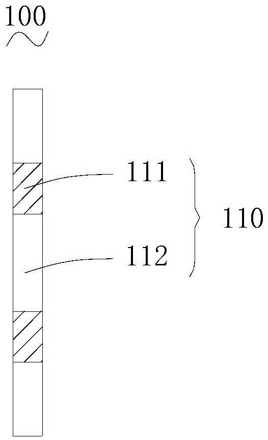
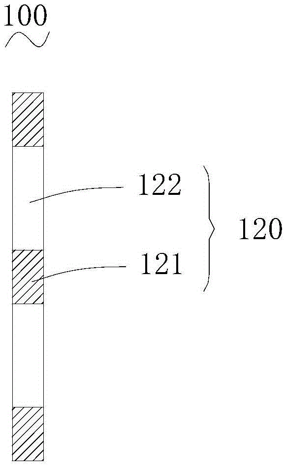
[0074] S20, providing a connecting piece, the connecting piece includes a first surface opposite to the front electrode and a second surface opposite to the back electrode.
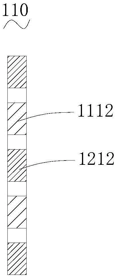
[0075] S30. Connect the front electrode to the first surface, form alternately arranged first connection regions and first non-connection regions on the first surface, connect the back electrodes of adjacent battery cut sheets to the second surface, and Alternately arranged second connection regions and second non-connection r...
Embodiment 1
[0096] See Figure 10 and Figure 11 The battery cutting sheet 200 that forms the solar cell module of this embodiment is formed by cutting the solar battery sheet into two equal parts. The back electrodes 220 are arranged at intervals along the length direction of the battery dicing sheet 200 . Both the front electrodes 210 and the back electrodes 220 are arranged at equal intervals.
[0097] Welding the front electrode 210 to the first connection area 111 on the first surface 110 of the connector 100, and then welding the back electrode 220 of the adjacent cell cut sheet 200 to the second connection area 121 on the second surface 120 of the connector 100 welding to obtain two battery cut sheets 200 overlapping in series, such as Figure 12 shown.
[0098] In this embodiment, the width of the back electrode 220 of the left battery cutting sheet 200 is slightly larger than the width of the front electrode 210 of the right battery cutting sheet 200, and the width of the con...
Embodiment 2
[0101] See Figure 13 and Figure 14 , the cell dicing sheet 300 constituting the solar cell module of this embodiment is cut in half from the solar cell sheet. The battery cutting sheet 300 includes a front electrode 310 and a back electrode 320 each extending along the length direction of the battery cutting sheet 300 . The front electrode 310 and the back electrode 320 are respectively located at edge positions of opposite ends of the battery cutting sheet 300 .
[0102] See Figure 15 , the connector 400 of this embodiment includes a first surface 410 connected to the front electrode and a second surface 420 connected to the back electrode. Alternately arranged first connection regions 411 and first non-connection regions 412 are arranged on the first surface 410 . Alternately arranged second connection regions 421 and second non-connection regions 422 are arranged on the second surface 420 . The projection of the first non-connected area 412 on the first surface 410 ...
PUM
Abstract
The invention relates to a solar cell module and a production method thereof. The solar cell module comprises a plurality battery cutting blades, which are serially connected together in an overlapped manner; and connecting members, which are used to serially connect the adjacent battery cutting blades. The battery cutting blades are cut by the solar cell pieces, and comprise front surface electrodes and back surface electrodes. Each of the connecting members comprises a first surface connected with the corresponding front surface electrode and a second surface connected with the corresponding back surface electrode, and the first surface is provided with first connection areas and first non-connection areas, which are arranged alternately, and the second surface is provided with second connection areas and second non-connection areas, which are arranged alternately, and in addition, the projections of the second connection areas on the first surface are covered by the projections of the first non-connection areas on the first surface. The front surface electrodes are connected with the first connection areas, and the back surface electrodes are connected with the second connection areas. By adopting the solar cell module, the elasticity of the solar cell module can be improved, and the gate-breaking and the cell-splitting are not easy to occur. The invention also provides the production method of the solar cell module.
Description
technical field [0001] The invention relates to the technical field of solar cells, in particular to a solar cell component and a preparation method thereof. Background technique [0002] As a new energy source, solar energy has the advantages of being inexhaustible, clean and environmentally friendly compared with traditional fossil fuels. At present, the main solar energy utilization method is to convert the received light energy into electrical energy output through solar cell components. The traditional solar cell component is formed by connecting several solar cells (or photovoltaic cells) in series and then packaging them in a square array. large-area battery components. Among them, the solar cell sheet absorbs light energy, and the accumulation of charges of opposite signs occurs at both ends of the battery, which generates "photovoltaic voltage", which is the "photovoltaic effect". Under the action of the photovoltaic effect, the two ends of the solar cell generate ...
Claims
Application Information
Patent Timeline
Application Date:The date an application was filed.
Publication Date:The date a patent or application was officially published.
First Publication Date:The earliest publication date of a patent with the same application number.
Issue Date:Publication date of the patent grant document.
PCT Entry Date:The Entry date of PCT National Phase.
Estimated Expiry Date:The statutory expiry date of a patent right according to the Patent Law, and it is the longest term of protection that the patent right can achieve without the termination of the patent right due to other reasons(Term extension factor has been taken into account ).
Invalid Date:Actual expiry date is based on effective date or publication date of legal transaction data of invalid patent.

