Integrated test system and integrated test method for fiber-optic network

A comprehensive test and optical fiber network technology, applied in transmission systems, electromagnetic wave transmission systems, electrical components, etc., can solve problems such as scattered test items, cumbersome test result data analysis and review, and inconvenient test items

Inactive Publication Date: 2016-05-18
INNO INSTR (CHINA) INC
View PDF5 Cites 24 Cited by
  • Summary
  • Abstract
  • Description
  • Claims
  • Application Information

AI Technical Summary

Problems solved by technology

[0003] The current optical fiber network test instruments have scattered test items and a single applicable test scenario. In actual use, testers generally test through various instruments, record the test results, and finally perform statistical analysis to test the items. The lack of concentration will cause the inconvenience of various project tests, and the analysis and consultation of the test result data is also very cumbersome, which increases the learning burden and working time of the operator
[0004] In addition, the existing optical fiber test methods also need to be improved

Method used


Image

  • Integrated test system and integrated test method for fiber-optic network
  • Integrated test system and integrated test method for fiber-optic network
  • Integrated test system and integrated test method for fiber-optic network

Examples


Embodiment Construction

[0050] In order to make the above objects, features and advantages of the present invention more comprehensible, specific implementations of the present invention will be described in detail below in conjunction with the accompanying drawings.

[0051]In the following description, numerous specific details are set forth in order to provide a thorough understanding of the present invention. However, the present invention can be implemented in many other ways different from those described here, and those skilled in the art can make similar extensions without violating the connotation of the present invention, so the present invention is not limited by the specific implementations disclosed below.

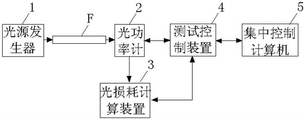
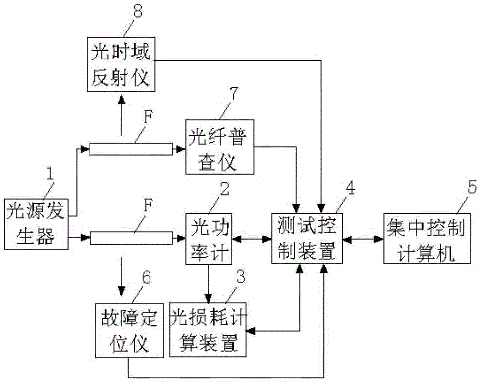
[0052] figure 1 An optical fiber network comprehensive test system according to an embodiment of the present invention is shown, including: a light source generator 1 , an optical power meter 2 , an optical loss calculation device 3 , a test control device 4 and a centralized control...


PUM


Abstract

The invention provides an integrated test system for a fiber-optic network. The system comprises a light source generator used for being connected with a first end interface of a to-be-measured optical fiber and sending a test light source, wherein the wave length of the test light source is selectable; an optical power meter used for being connected with the second end interface of the to-be-measured optical fiber, receiving the test light source and conducting the test on the relative power/absolute power to obtain the test result on the optical power of the to-be-measured optical fiber, wherein the wave length of the test light source is 1310 nm or 1550 nm during the testing process of the optical power meter; a light loss computing device used for calculating the difference value of the optical power as the test result on the light loss of the to-be-measured optical fiber based on the test result of the optical power meter on the test light source; a test control device used for controlling the operation of the system and receiving all the above test results to form a test report; and a centralized control computer used for receiving the test report updated by the above test control device. Based on the above integrated test system and the above integrated test method, the integrated test can be realized. Meanwhile, the system and the method can be applied in different test scenarios to generate a unified rest report for remote transmission. In this way, the remote centralized monitoring is realized.

Description

technical field [0001] The invention relates to the field of optical fiber communication, in particular to an optical fiber network comprehensive testing system and a comprehensive testing method. Background technique [0002] Optical fiber network testing is to detect the performance and quality of optical fiber cable wiring network; it is widely used in optical fiber communication network, integrated wiring system, optical device production and research; generally speaking, for optical network, the performance requirements are very high, testing There are many projects. [0003] The current optical fiber network test instruments have scattered test items and a single applicable test scenario. In actual use, testers generally test through various instruments, record the test results, and finally perform statistical analysis to test the items. The lack of centralization will cause inconvenience to various project tests, and the analysis and review of test result data is als...

Claims


Application Information

Patent Timeline
Patent Type & Authority Applications(China)
IPC IPC(8): H04B10/079H04B10/073
CPCH04B10/0731H04B10/0791H04B10/07955H04B10/07957
Inventor 李楚元
Owner INNO INSTR (CHINA) INC
Why Eureka
Try Eureka