
Optical module and method for adjusting input optical power of optical module

A technology of optical module and optical input, which is applied in the field of optical communication to achieve the effect of convenient use and good stability

Inactive Publication Date: 2016-05-18
ZTE CORP
View PDF6 Cites 2 Cited by
  • Summary
  • Abstract
  • Description
  • Claims
  • Application Information

AI Technical Summary

Problems solved by technology

[0004] The main purpose of the present invention is to solve the technical problem of remotely adjusting the input optical power of the optical module

Method used


Image

  • Optical module and method for adjusting input optical power of optical module
  • Optical module and method for adjusting input optical power of optical module
  • Optical module and method for adjusting input optical power of optical module

Examples


Embodiment Construction

[0045] It should be understood that the specific embodiments described here are only used to explain the present invention, not to limit the present invention.

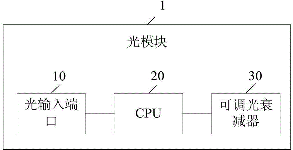
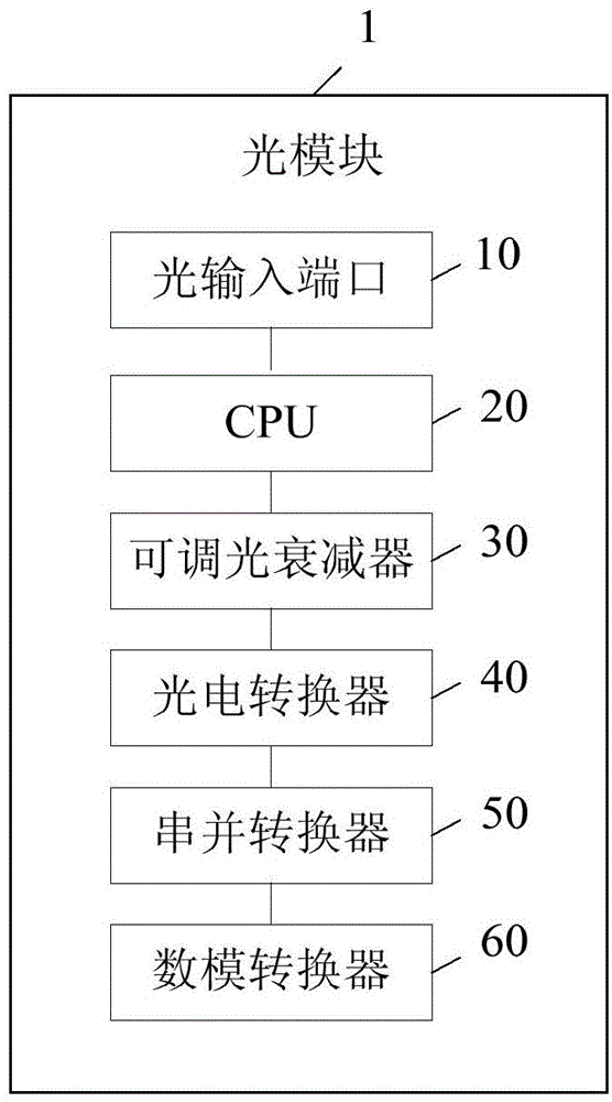
[0046] The present invention provides an optical module, referring to figure 1 , in one embodiment, the optical module 1 includes an electrically connected optical input port 10, a CPU (Central Processing Unit, central processing unit) 20 and an adjustable optical attenuator 30, and the adjustable optical attenuator 30 is used to The attenuation command received by the CPU 20 acquires the attenuation value of the optical signal received from the optical input port 10, so as to perform attenuation processing on the optical signal.

[0047] In this embodiment, by setting the optical input port 10, the CPU 20 and the adjustable optical attenuator 30 electrically connected, the adjustable optical attenuator 30 obtains the light received from the optical input port 10 according to the attenuation command received by the CP...


PUM


Abstract

The invention discloses an optical module comprising an optical input port, a CPU and an adjustable optical attenuator, all of which are electrically connected. The adjustable optical attenuator is used for acquiring the attenuation value of an optical signal received from the optical input port according to an attenuation command received by the CPU. The invention further discloses a method for adjusting the input optical power of an optical module. According to the invention, by arranging an optical input port, a CPU and an adjustable optical attenuator which are electrically connected and using the adjustable optical attenuator to acquire the attenuation value of an optical signal received from the optical input port according to an attenuation command received by the CPU and to attenuate the optical signal, remote adjustment of the input optical power of an optical module is realized. Thus, field debugging by testers due to deviation of the input optical power is omitted, and detection is time-saving and labor-saving. In addition, the adjustable optical attenuator is of high stability, and is easy to use.

Description

technical field [0001] The invention relates to the technical field of optical communication, in particular to an optical module and a method for adjusting the input optical power of the optical module. Background technique [0002] In the laboratory or the engineering site where the networking environment is set up for the operator, a large number of optical modules with various speeds will be used in the optical monitoring of optical transmission, the client-side single board and the line-side single board. When debugging an optical path, engineers usually need to go to the site to measure the input optical power with an optical power meter. If the optical power does not meet the requirements, a fixed attenuator will be added to the input port to adjust the input optical power to an appropriate range (PIN The diode is adjusted below 0dBm, and the avalanche photodiode APD is adjusted below -9dBm). However, the quality of the fixed attenuators currently on the market is not...

Claims


Application Information

Patent Timeline
Patent Type & Authority Applications(China)
IPC IPC(8): H04B10/40H04B10/564
CPCH04B10/67
Inventor 冯小财
Owner ZTE CORP
Learn More