Video monitoring control method and device

A technology of video monitoring and control devices, applied in the field of communication, can solve the problems of monitoring camera equipment control delay and long transmission path of control instructions, etc., and achieve the effect of reducing control delay and shortening the transmission path

Inactive Publication Date: 2016-05-18
HUAWEI TECH CO LTD
View PDF4 Cites 1 Cited by
  • Summary
  • Abstract
  • Description
  • Claims
  • Application Information

AI Technical Summary

Problems solved by technology

[0005] The embodiment of the present invention provides a video monitoring control method and device, which solves the problem of long control instruction transmission path and delay in the control of the monitoring camera equipment by the monitoring center in the prior art

Method used


Image

  • Video monitoring control method and device
  • Video monitoring control method and device
  • Video monitoring control method and device

Examples


Embodiment Construction

[0062] The following will clearly and completely describe the technical solutions in the embodiments of the present invention with reference to the accompanying drawings in the embodiments of the present invention. Obviously, the described embodiments are only some, not all, embodiments of the present invention. Based on the embodiments of the present invention, all other embodiments obtained by persons of ordinary skill in the art without creative efforts fall within the protection scope of the present invention.

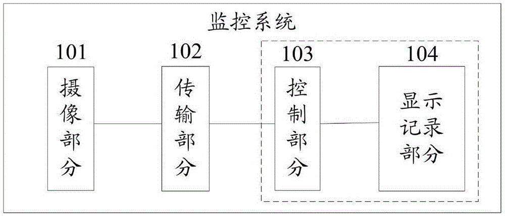
[0063] The system architecture of the monitoring system applied in the embodiment of the present invention is as follows figure 1 As shown, the system architecture is composed of four parts: the camera part 101 , the transmission part 102 , the control part 103 , and the display record part 104 .

[0064] Among them, the camera part 101 is the front part of the monitoring system and the "eye" of the whole system. It is arranged at a certain position of the monitore...


PUM


Abstract

One embodiment of the invention provides a video monitoring control method and device and relates to the technical field of communication, solving the problems of long transmission path of control commands and delay of a control center's control on a monitoring and image pick-up device The method comprises following steps: a terminal sends video RTCP messages to the monitoring and image pick-up device, wherein the video RTCP messages carry control commands of the monitoring and image pick-up device; after the monitoring and image pick-up device receives the video RTCP messages, the video RTCP messages are analyzed to obtain the control commands of the monitoring and image pick-up device; and on the basis of the control commands, the monitoring and image pick-up device is controlled.

Description

technical field [0001] The present invention relates to the field of communication technology, in particular to a video surveillance control method and device. Background technique [0002] With the rapid development of communication technology, the application of video surveillance is more and more extensive. For example, surveillance cameras are installed in places such as roads, hospitals, supermarkets, communities or private houses. The collected video images are sent to the monitoring center, and the monitoring center can also control the monitoring camera, such as adjusting the direction of the camera, the clarity of the collected images, etc., so as to realize real-time monitoring of these places. [0003] At present, when the monitoring center controls the monitoring camera, it is usually sent through the message of the session initiation protocol SIP signaling, that is, the monitoring center places the control command of the monitoring camera in the message of the S...

Claims


Application Information

Patent Timeline
Patent Type & Authority Applications(China)
IPC IPC(8): H04L29/06H04N7/18
CPCH04N7/181H04L65/65
Inventor 刘宏图
Owner HUAWEI TECH CO LTD
Why Eureka
Try Eureka