Method and system for projector calibration

A technology for projectors and laser projectors, which is used in the field of projector calibration and systems, and can solve problems such as inaccuracy

Active Publication Date: 2016-05-18
DISNEY ENTERPRISES INC
View PDF5 Cites 17 Cited by
  • Summary
  • Abstract
  • Description
  • Claims
  • Application Information

AI Technical Summary

Problems solved by technology

[0004] However, known calibration techniques for laser projectors require exte

Method used


Image

  • Method and system for projector calibration
  • Method and system for projector calibration
  • Method and system for projector calibration

Examples


Embodiment Construction

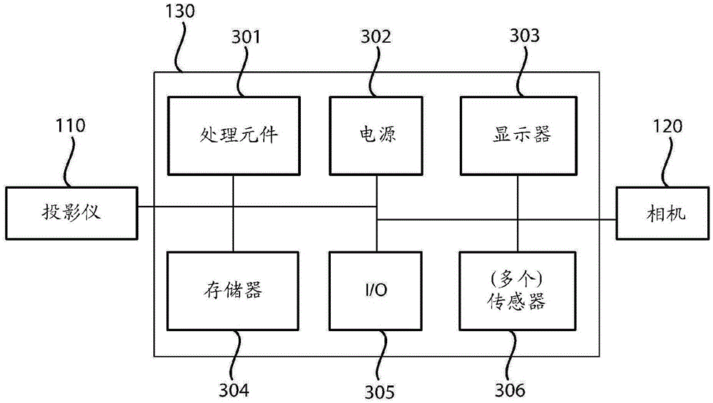
[0036] Turning now to the figures, the calibration methods and systems of the present disclosure will now be discussed in greater detail. figure 1 is a perspective view of the calibration system 10 . figure 2 is a simplified block diagram of the calibration system 10 . refer to figure 1 with 2 , the calibration system 10 may include one or more laser projectors 110 , a projection surface 161 , one or more cameras 120 a , 120 b , and one or more computers 130 . The one or more laser projectors 110, cameras 120a, 120b, and computer 130 may all be in electrical communication with each other and / or include the ability to share and transfer information between each device. Each component will be discussed in order below.

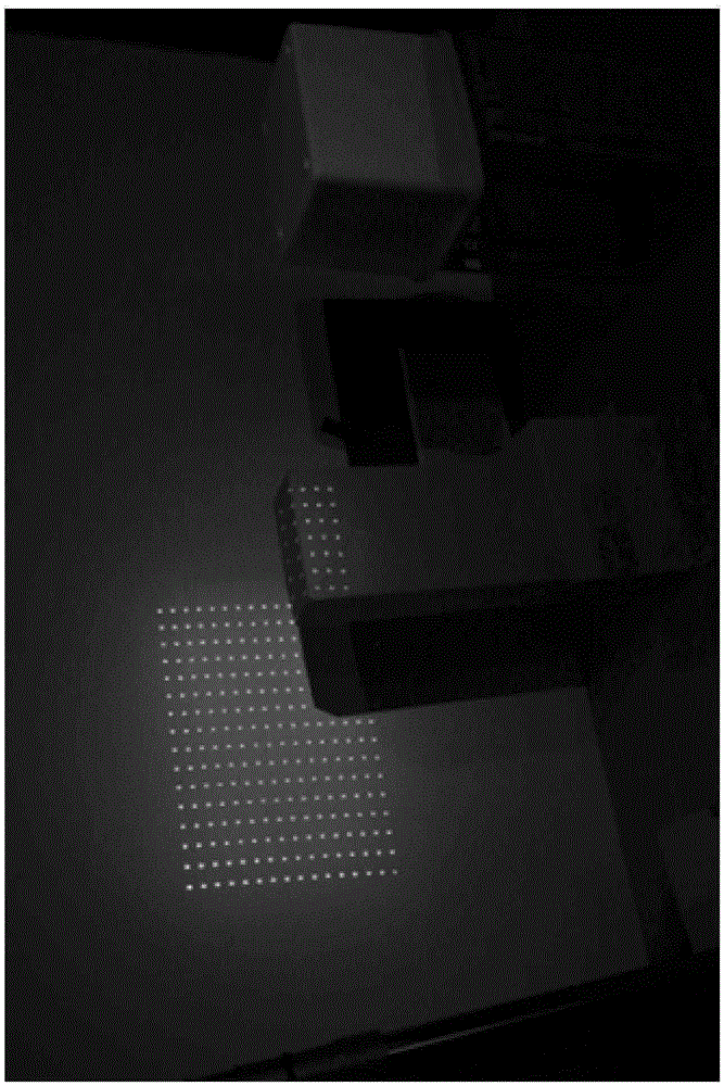
[0037] Projection surface 161 may be substantially any type of opaque surface or object. For example, projection surface 161 may be flat, non-planar, or varied and may include one or more textures or surface variations and / or colors. In some examples, proj...


PUM


Abstract

The present disclosure relates to a method for calibrating a projector. The method includes projecting a test pattern onto a scene or an object within the scene and capturing the test pattern using a camera. Once the test pattern image has been captured by the camera, the method further includes estimating by a processing element a perspective projection matrix, warping the estimated projection matrix based on a non-linear distortion function, and modifying the projector to project light based on the distortion function. The present disclosure also relates to a presentation or projection system including two types of projectors for projecting an output presentation having a second image overlaid on a first image.

Description

technical field [0001] The techniques described herein generally relate to methods and systems for calibrating one or more projectors. Background technique [0002] Image projectors may be used to project images onto a projection surface such as a screen or other surface. In some applications, video projectors can be used to enhance, compliment, or otherwise augment objects on surfaces to create a dynamic and pleasing user experience, such as like an amusement park attraction. For example, characters or objects that virtually "interact" with real objects on the surface can be projected on the surface. [0003] Conventional video projectors have several limitations. In particular, conventional video projectors have limited color gamut and brightness. Due to these limitations, presentations using only conventional video projectors can look dull and monotonous. Additionally, in situations where ambient lighting is present, the resulting image may appear washed out and unrea...

Claims


Application Information

Patent Timeline
IPC IPC(8): H04N17/00G01R35/00
CPCG01B11/2504G01B11/2513G06T3/0093H04N9/3185H04N9/3194
Inventor A.格伦赫菲尔
Owner DISNEY ENTERPRISES INC
Why Eureka
Try Eureka