Optical unit that has image stabilization functionality

A technology for jitter correction and optical units, which is applied to optical components, optical, electrical components, etc., and can solve problems such as the size of optical units becoming larger

Active Publication Date: 2016-05-18
SANKYO SEIKI MFG CO LTD
View PDF8 Cites 14 Cited by
  • Summary
  • Abstract
  • Description
  • Claims
  • Application Information

AI Technical Summary

Problems solved by technology

Therefore, it is necessary to arrange enough space in the direction perpendicular to the optical axis direction around the optical module, so there is a problem that the dimension of the optical unit in the direction perpendicular to the optical axis direction becomes large.

Method used


Image

  • Optical unit that has image stabilization functionality
  • Optical unit that has image stabilization functionality
  • Optical unit that has image stabilization functionality

Examples


Embodiment Construction

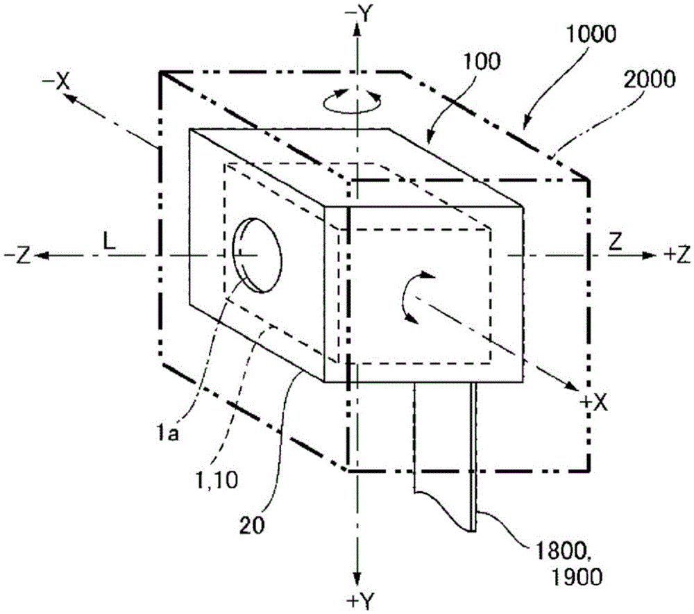
[0074] Hereinafter, modes for implementing the present invention will be described with reference to the drawings. In addition, in the following description, the structure for preventing the hand shake of the optical module for photographing is shown as an example. And, in the following description, the three directions orthogonal to each other are respectively referred to as the X-axis direction, the Y-axis direction and the Z-axis direction, and the first direction along the optical axis L (lens optical axis / optical axis of the optical element) is referred to as In the Z-axis direction, the second direction intersecting the Z-axis direction (first direction) is taken as the Y-axis direction, and the third direction intersecting the Z-axis direction (first direction) and the Y-axis direction (second direction) is taken as X axis direction. In addition, in the following description, among shakes in various directions, rotation around the X-axis corresponds to so-called pitch ...


PUM


Abstract

To provide an optical unit that has image stabilization functionality, wherein even if a movable module is pivotably supported at a point partway down said movable module in the direction of the optical axis, the center of gravity of the movable module in the direction of the optical axis can be effectively moved closer to the point at which the movable module is supported. In this optical unit (100), a gimbal mechanism (30) (support mechanism) pivotably supports a movable module (10) at a point partway down said movable module (10) in a Z-axis direction. The movable module (10) comprises an optical module (1) and a weight (5). The optical module (1) holds a lens (1a), and the weight (5) is attached to the front end (1c) of the optical module (1) in the direction of the optical axis (L). The center of gravity of the movable module (10) in the direction of the optical axis (L) can thus be shifted from the location of the center of gravity of the optical module (1) towards the point at which the gimbal (30) supports the movable module (10). The front end surface (51a) of the weight (5) in the direction of the optical axis (L) is flat and perpendicular to the optical axis (L).

Description

technical field [0001] The present invention relates to an optical unit with a shake correction function installed in a mobile phone with a camera or the like. Background technique [0002] In recent years, mobile phones have been configured as optical devices equipped with an optical unit for photographing. In this optical unit, in order to suppress disturbance of a captured image due to user's hand shake, a configuration is proposed in which the shake is corrected by swinging the optical module. In order to perform such shake correction, it is necessary to support the optical module so as to be able to swing relative to the fixed body. [0003] Therefore, a structure has been proposed in which the optical module is supported swingably by a pivot provided on the rear side of the optical axis direction of the optical module, and the optical module is swung around the pivot to correct the shake of the optical unit (see Patent Document 1, 2). [0004] However, in the case o...

Claims


Application Information

Patent Timeline
Patent Type & Authority Applications(China)
IPC IPC(8): G03B5/00G03B17/56H04N5/225H04N5/232
CPCG03B5/00G03B2205/0007G02B7/023G02B27/644H04N23/57H04N23/687G02B5/00
Inventor 南泽伸司
Owner SANKYO SEIKI MFG CO LTD
Why Eureka
Try Eureka