A vertical walking mechanism

A walking mechanism, vertical technology, applied in metal processing machinery parts, driving devices, metal processing equipment and other directions, can solve the problem of inability to guarantee the straightness and straightness of the mechanical arm, reduce the floor space, expand the work space, The effect of improving quality

Active Publication Date: 2018-03-20
广东泰格威机器人科技有限公司
View PDF6 Cites 0 Cited by
  • Summary
  • Abstract
  • Description
  • Claims
  • Application Information

AI Technical Summary

Problems solved by technology

[0005] The purpose of the present invention is to overcome the shortcomings and deficiencies in the prior art, and provide a vertical walking mechanism, which can effectively solve the problem that the straightness and straightness of the mechanical arm walking motion cannot be guaranteed due to uneven ground, thereby improving The quality of the manipulator clamping the profile for processing; at the same time, the walking mechanism can reduce the floor space occupied by the manipulator movement

Method used


Image

  • A vertical walking mechanism
  • A vertical walking mechanism
  • A vertical walking mechanism

Examples


Embodiment 1

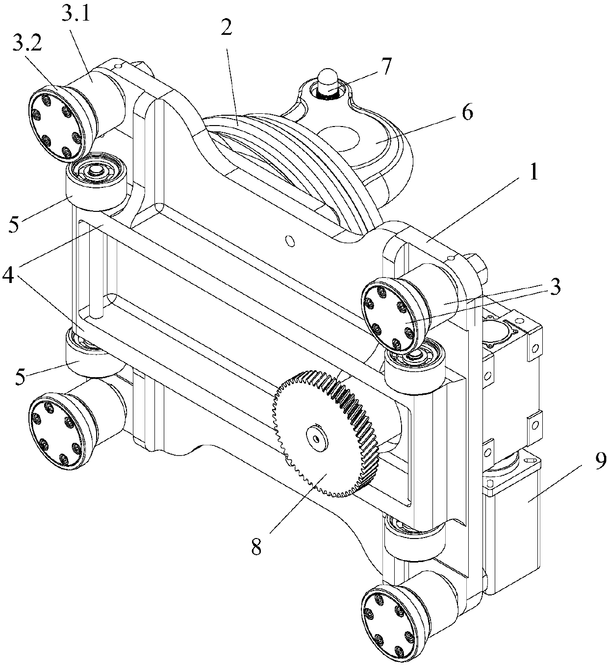
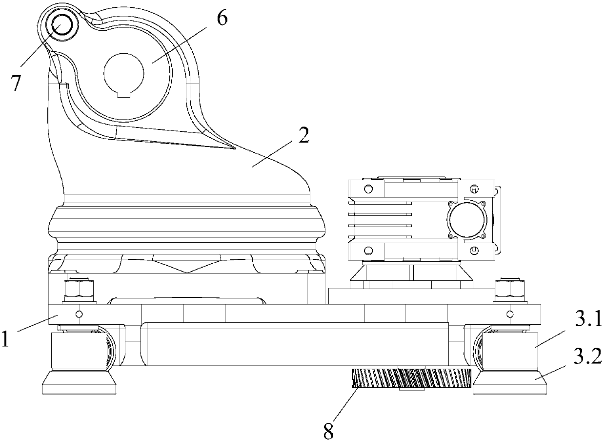
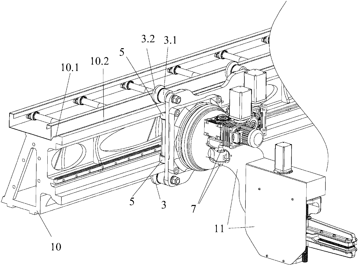
[0026] Such as Figure 1 to Figure 3 As shown, the vertical walking mechanism of the present invention is used to slide and connect with the vertical track 10 to realize the walking movement of the mechanical arm 11. The walking mechanism includes a frame body 1 and a base 2 for installing the mechanical arm 11, wherein the base 2. One end is detachably connected to the frame body 1, and the other end is used to connect the mechanical arm 11. There is a sliding device at the bottom of the frame body 1. The sliding device is used to buckle on the slide rail on the side of the vertical track 10 and slide to connect with the slide rail , to realize that the frame body 1 is suspended on the side of the vertical track 10 for walking and moving.

[0027] The sliding device of the present invention is the guide wheels 3 respectively arranged at the four top corners of the bottom of the frame body 1, and the guide wheels 3 opposite up and down on the same side are used to snap on the ...

Embodiment 2

[0032] The difference between this embodiment and Embodiment 1 is that the guide wheels of the present invention can be provided with six or eight etc. according to the specifications of the frame body, and the guide wheels are distributed symmetrically at the bottom of the frame body up and down, and the relative guide wheels up and down are used It is buckled on the slide rail on the side of the vertical track and slidably connected with the slide rail. In this embodiment, the upper and lower opposite guide wheels can be snapped onto the slide rails on the side of the vertical track to realize the stable suspension and movement of the frame body.

[0033] Similarly, one, two, three or more support wheels can be set according to requirements, so as to achieve positioning and avoid deviations in the walking of the frame body, and can further ensure the straightness and flatness of the movement of the mechanical arm installed on the walking mechanism .

[0034] Other structure...


PUM


Abstract

The invention provides a vertical travel mechanism. The vertical travel mechanism is used for being slidably connected with a vertical track, so that a mechanical arm can travel and move. The vertical travel mechanism comprises a frame and a base. The base is used for mounting the mechanical arm; one end of the base is detachably connected with the frame, and the other end of the base is used for being connected with the mechanical arm; a sliding device is arranged at the bottom of the frame and is used for being clipped on slide rails on the side surfaces of the vertical track and is slidably connected with the slide rails, so that the frame can be suspended on the side surfaces of the vertical track and can travel and move. The vertical travel mechanism has the advantages that the problem that the travel and movement straightness and flatness of an existing mechanical arm cannot be guaranteed due to uneven grounds can be effectively solved, and accordingly the machining quality of section bars clamped by the mechanical arm can be improved; movement occupied spaces of the mechanical arm can be reduced by the aid of the vertical travel mechanism.

Description

technical field [0001] The invention relates to the technical field of metal processing, and more specifically relates to a vertical traveling mechanism. Background technique [0002] The robotic arm is often used in the process of object handling and can replace manpower to work. In an environment that is unfavorable to the human body, it can replace people to work and maintain personal safety. The mechanical arm is mainly composed of three parts: the actuator, the driving mechanism and the control mechanism. The arm is used to grasp the workpiece. It adopts various structural forms according to the shape, size, weight and material of the grasped piece. Such as adsorption type, holding type and clamping type and so on. [0003] Usually, the mechanical arm needs to use the walking mechanism to realize its flexible movement and walking during the processing process, which greatly expands the working space of the mechanical arm. And the walking mechanism of existing mechanic...

Claims


Application Information

Patent Timeline
Patent Type & Authority Patents(China)
IPC IPC(8): B23Q5/02
CPCB23Q5/02
Inventor 卢新建廖子剑唐崇斌
Owner 广东泰格威机器人科技有限公司
Why Eureka
Try Eureka