Rebar prying hook

A technology of steel bars and hooks, applied in the field of construction auxiliary construction tools, can solve problems such as affecting work efficiency, and achieve the effects of improving work efficiency, improving construction quality and simple structure

Inactive Publication Date: 2016-05-25
GUANGDONG SHUNDE HUAYAN ELECTRONICS TECH CO LTD
View PDF8 Cites 1 Cited by
  • Summary
  • Abstract
  • Description
  • Claims
  • Application Information

AI Technical Summary

Problems solved by technology

However, at present, most construction sites use steel bars to stick to the formwork before pouring concrete. There is not enough space between the steel bars and the formwork for the steel bar binding machine to operate, which gives this kind of intelligence that can greatly improve work efficiency. Tools bring obstacles that seriously affect their work efficiency

Method used


Image

  • Rebar prying hook
  • Rebar prying hook
  • Rebar prying hook

Examples


Embodiment 1

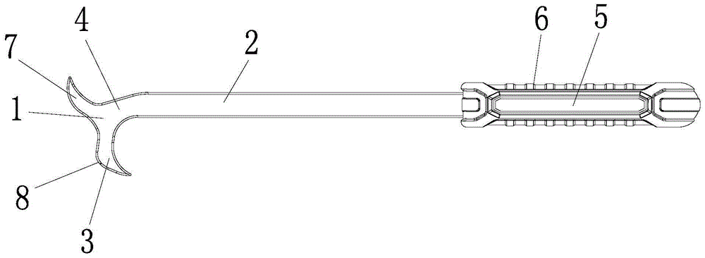
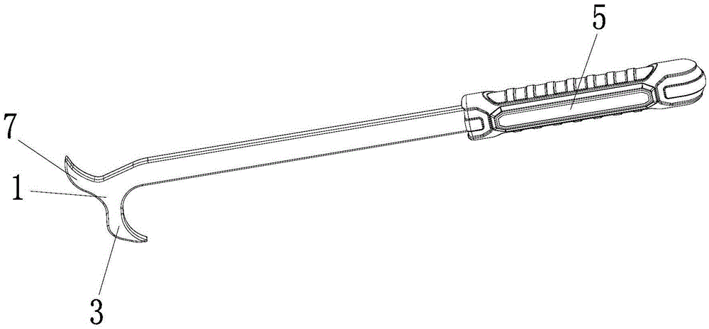
[0023] A steel bar prying hook, comprising a hook body 1 and a hook bar 2, the hook body is arranged at one end of the hook bar.

[0024] Preferably, the hook body has two hooks, and the two hooks are arranged on the hook rod to form an "r"-shaped structure.

[0025] Preferably, the hook body includes two crotches and a crotch connecting rod 4, the two crotches are respectively arranged on opposite sides of the crotch connecting rod and the two crotches protrude outwards in opposite directions, the The crotch connecting rod is connected with the hook rod.

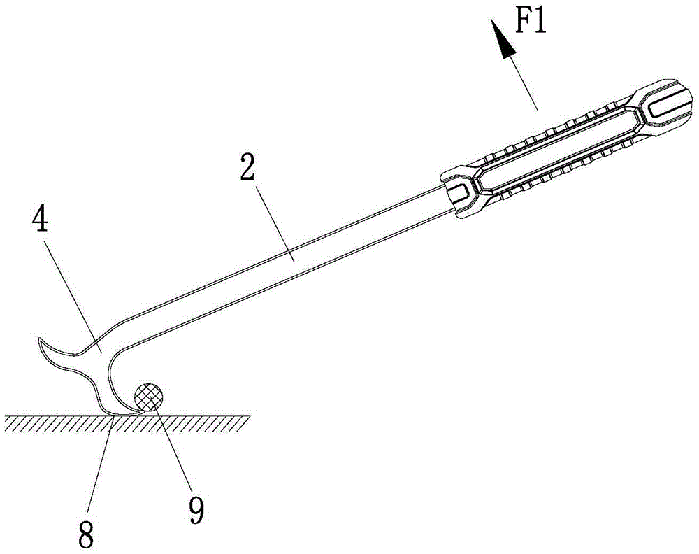
[0026] In order to pry up the steel bars more conveniently, preferably, the hook connecting rod protrudes obliquely toward one of the hooks, and an included angle of 150°-175° is formed between the hook connecting rod and the hook rod.

[0027] Preferably, one of the two crotches is a support pry hook 3 capable of supporting and prying up the steel bar 9, and the other is a pry hook 7, and the support part 8 is provided on...


PUM


Abstract

The invention discloses a rebar prying hook which comprises a hook body and a hook rod. The hook body is arranged at one end of the hook rod and comprises two hooks which are arranged on the hook rod to form an r-shaped structure. By using the rebar prying hook, a rebar and a formwork can be pulled apart for enough distance to enable a rebar binding machine to run smoothly, so that original performance of the rebar binding machine is brought into full play and working efficiency and construction quality are improved greatly. In addition, the two hooks are arranged, so that a user can flexibly use one of the hooks according to habits and environments and can use the other one as a fulcrum to realize labor saving effect. The rebar prying hook has the advantages of simple structure, easiness in use, light weight and convenience.

Description

technical field [0001] The invention relates to an auxiliary building construction tool, in particular to a steel bar prying hook. Background technique [0002] With the adjustment of modern population structure and industrial transformation, more and more industrial automation equipment and tools are being continuously promoted and applied, and the steel bar binding machine is undoubtedly a new star in the automation tools of the construction industry. However, at present, most construction sites use steel bars to stick to the formwork before pouring concrete. There is not enough space between the steel bars and the formwork for the steel bar binding machine to operate, which gives this kind of intelligence that can greatly improve work efficiency. Tools bring obstacles that seriously affect their work efficiency. Contents of the invention [0003] Aiming at the technical problems existing in the prior art, the object of the present invention is to provide a steel bar cr...

Claims


Application Information

Patent Timeline
Patent Type & Authority Applications(China)
IPC IPC(8): E04G21/12
CPCE04G21/12
Inventor 易映国李移清
Owner GUANGDONG SHUNDE HUAYAN ELECTRONICS TECH CO LTD
Why Eureka
Try Eureka