Vibration scratch detection method

A detection method and wheel abrasion technology, applied in the field of detection, can solve problems such as easy misjudgment, unavoidable influence, breakage, etc., and achieve the effect of protecting life and property, ensuring driving safety, and ensuring driving safety.

Active Publication Date: 2019-04-23
DONGGUAN NANNAR ELECTRONICS TECH +1
View PDF4 Cites 0 Cited by
  • Summary
  • Abstract
  • Description
  • Claims
  • Application Information

AI Technical Summary

Problems solved by technology

[0002] During the operation of the train, the wheel tread is often partially scratched due to braking or idling slippage. When the scratched wheel runs between the wheel and rail, an additional wheel-rail impact force will be generated, and its size varies with the length and depth of the scratch and the speed of the train. Several times to dozens of times the static load of the wheel, and with the rolling of the wheel, it periodically acts on the track and the vehicle system, causing coupling vibration of the entire vehicle track system, and even fracture of the wheel axle, rail and sleeper, etc., seriously affecting the train. Safety and service life of track facilities
[0003] The existing wheel tread scratch detection technology is mainly ground detection, and the force-measuring rail is used most in the ground detection method. However, the number of strain gauges arranged on the track is limited, and the wheel scratch position just acts on the strain gauge installation. Low probability, easy to miss
Due to the larger response range of the vibration sensor, some detection systems install acceleration sensors on the track to replace the strain gauges. However, this method is difficult to avoid the influence of adjacent wheels and is prone to misjudgment.

Method used


Image

  • Vibration scratch detection method
  • Vibration scratch detection method
  • Vibration scratch detection method

Examples


Embodiment Construction

[0026] In order to make the technical solution of the present invention more clearly expressed, the present invention will be further described below in conjunction with the accompanying drawings.

[0027] A method for detecting vibration scratches, identifying wheel scratches by detecting the up and down vibration amplitude of a track during vehicle operation, comprising the following steps:

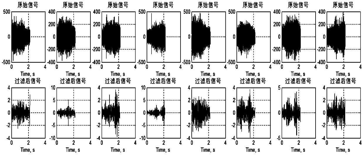
[0028] Step (1): Detect impact signal, provide several sensors, these several sensors are distributed on the same side of track, in the present embodiment, the quantity of described sensor is eight; The abrasion on the train wheel can cause the wheel to run on the track. There is a bumpy motion, and this motion will be transmitted to the track, and the sensor will detect this bumpy motion and convert the vibration amplitude of the track into an electrical signal, and the sensors will respectively extract eight groups of different electrical signals.

[0029] Step (2): filter processing,...


PUM


Abstract

A vibration scratch detection method for detecting wheel scratches, comprising the following steps: (1): detection of impact signals, (2): filtering processing, (3): normalization processing, (4): kurtosis statistics , (5): scratch processing, (6): maximum value processing, (7): simultaneous processing on the same track, (8): threshold value processing and scratch judgment, and those that meet a certain threshold are regarded as scratches; the vibration of the present invention The scratch detection method adopts the sensor to sense the bumpy amplitude of the track and forms an impact signal, and then performs signal processing on the impact signal as in the aforementioned steps to determine the wheel scratch position, which is convenient for correct maintenance of the wheel and ensures that the driving Safety. The entire detection process does not require manual participation, saves labor, has strong practicability, and can monitor the train in real time to provide valuable data for maintenance, and can understand faults in time, prevent the occurrence of faults, ensure driving safety, and protect the lives of passengers. property protection.

Description

technical field [0001] The invention relates to a detection method, in particular to a detection method for wheel vibration scratches. Background technique [0002] During the operation of the train, the tread of the wheel is often partially scratched due to braking or idling and slipping. When the scratched wheel runs between the wheel and the rail, an additional wheel-rail impact force will be generated, and its size varies with the length and depth of the scratch and the speed of the train. Several times to dozens of times the static load of the wheel, and with the rolling of the wheel, it periodically acts on the track and the vehicle system, causing coupling vibration of the entire vehicle track system, and even fracture of the wheel axle, rail and sleeper, etc., seriously affecting the train. The safety and service life of track facilities. [0003] The existing wheel tread scratch detection technology is mainly ground detection, and the force-measuring rail is used m...

Claims


Application Information

Patent Timeline
Patent Type & Authority Patents(China)
IPC IPC(8): G06K9/00
CPCG06F2218/10G06F2218/04G06F2218/12
Inventor 谭志忠杨马生
Owner DONGGUAN NANNAR ELECTRONICS TECH
Why Eureka
Try Eureka