Supercharge Your Innovation With Domain-Expert AI Agents!

Manufacturing method of automatic cleaning device

A technology of automatic cleaning and manufacturing methods, applied in the mechanical field of washing or cleaning, which can solve the problems that the amount of cleaning liquid cannot be adjusted, the time-consuming cleaning process increases, and the control range of injection volume is small.

Inactive Publication Date: 2016-06-01
郑子繁
View PDF6 Cites 8 Cited by
  • Summary
  • Abstract
  • Description
  • Claims
  • Application Information

AI Technical Summary

Problems solved by technology

[0002] The current sweeping machines, floor washing machines, window cleaning machines and curtain wall cleaning machines use rags to rub the surface to be cleaned. Since there is no water or detergent (hereinafter collectively referred to as cleaning liquid) to participate, stains cannot be effectively removed
[0003] Or the rag is soaked with cleaning liquid, rubbed on the surface to be cleaned, and the cleaning liquid in the rag is used to infiltrate synchronously when it moves to the cleaning area. For the surface to be cleaned that needs to be infiltrated in advance, the cleaning process will take longer
[0004] The current method of rag soaking is to connect the container with the cleaning liquid through the capillary, and use the capillary phenomenon of the rag to make the cleaning liquid soak into the rag, but the rag is supplied with liquid through the capillary, and the amount of cleaning liquid supplied cannot be adjusted, which may easily cause overwetting on the rag Or too dry, forming water spots and poor cleaning effect
[0005] Or the brush roller and the nozzle cooperate to clean the object to be cleaned. There is a hole on the nozzle pipe, and the cleaning liquid is sprayed from the hole to the brush roller or the surface to be cleaned through the pressure. When the pressure is small, the range of the sprayed liquid becomes smaller, and finally flows on the surface of the nozzle, which cannot be effectively sprayed to the surface to be cleaned, and is easy to leave water stains on the surface to be cleaned. When the pressure increases, the sprayed liquid flows on the surface to be cleaned It is easy to splash, and the above phenomenon will occur when the nozzle starts and stops, which will affect the cleaning effect

Method used


Image

  • Manufacturing method of automatic cleaning device
  • Manufacturing method of automatic cleaning device
  • Manufacturing method of automatic cleaning device

Examples


Embodiment 1

[0041] Embodiment one, see Figure 1-Figure 15 .

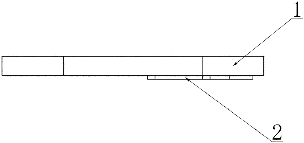
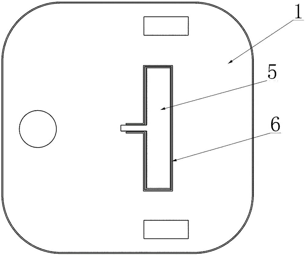
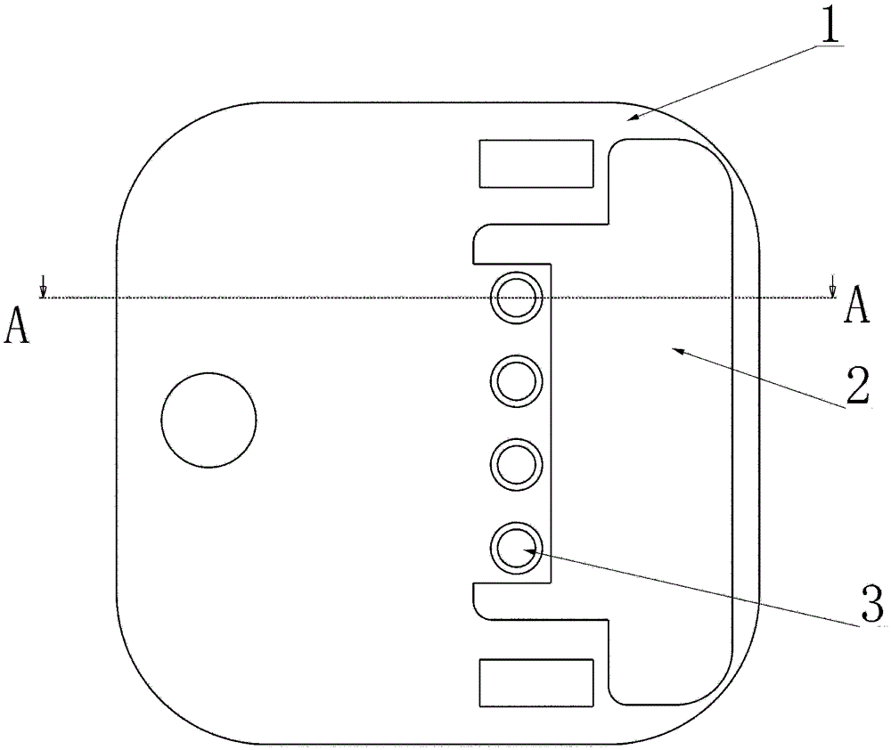
[0042] The manufacturing method of the automatic cleaning device in this embodiment is used for cleaning devices such as floor sweepers and window cleaners, and is mainly composed of a rag 2, a microporous atomizing sheet 3, and a housing 1; other accessories include a microporous atomizing sheet pressing plate 4, Capillary liquid guide strip 5, liquid guide tank (tube) 6, microporous atomizing sheet drive power supply, water tank, etc.

[0043] The cleaning liquid is transferred to the microporous atomizing sheet 3 along the liquid guide groove (tube) 6 and the capillary liquid guiding strip 5, and the microporous atomizing sheet 3 is driven by the driving power to spray the cleaning liquid in a mist form.

[0044] Due to different automatic cleaning machinery and devices, such as Figure 10 , Figure 11 As shown, the mop can take different shapes and installation forms.

[0045] Figure 10 , Figure 12 , the rag is not...

Embodiment 2

[0052] Embodiment two, see Figure 16-Figure 22 .

[0053] The manufacturing method of the automatic cleaning device in this embodiment can be applied to cleaning devices such as floor sweepers, window cleaning machines, and floor washing machines; it mainly consists of a brush roller 9, a microporous atomizing sheet 3, and a housing 1; other accessories include micro Porous atomizing sheet pressure plate 4, capillary liquid guiding strip 5, liquid guiding groove 6, brush roller driving mechanism, microporous atomizing sheet driving power supply, water tank, etc.

[0054] Such as Figure 22 As shown, when the device mainly moves horizontally (such as a mopping machine and a sweeping machine), the cleaning liquid flows through the liquid guide groove 6 where the capillary liquid guide strip 5 is located and is filled to a suitable height, and the capillary liquid guide strip 5 is in the device. It plays the role of guiding the liquid, and also prevents excessive cleaning liqu...


PUM


Abstract

The invention relates to a manufacturing method of an automatic cleaning device. The manufacturing method is characterized in that the automatic cleaning device is manufactured by utilizing two characteristics of a fine atomized state of cleaning liquid jetted by microporous atomization pieces and the adjustable total jet quantity within a certain time. The automatic cleaning device is mainly formed by the microporous atomization pieces, a cleaning component and a shell, wherein the microporous atomization pieces are located at a cleaning component side of a contact surface formed by the cleaning component and a to-be-cleaned surface; the cleaning component is located between the shell and the to-be-cleaned surface; the cleaning component comprises cleaning cloth, a brush roller and a component which is in contact with the to-be-cleaned component and is used for cleaning. The invention relates to a washing or cleaning machine applied to a family, in particular to automatic cleaning machines such as a motorized machine (sweeper) which is used for cleaning floors, a machine (a window cleaning robot) which is used for cleaning windows, a machine which is used for cleaning walls (curtain walls) and the like. According to the automatic cleaning device manufactured by the manufacturing method, the cleaning efficiency is increased, the consumption of the cleaning liquid is reduced, and the burden of a user is relieved.

Description

technical field [0001] The invention relates to a manufacturing method of an automatic cleaning device. The method is applied to household washing or cleaning machines, especially motorized floor washing machines (sweepers), window cleaning (glass-cleaning robots), walls (curtain walls) ) Manufacturing of cleaning and other machinery. Background technique [0002] The current sweeping machines, floor washing machines, window cleaning machines and curtain wall cleaning machines use rags to rub the surface to be cleaned. Since there is no water or detergent (hereinafter collectively referred to as cleaning liquid) to participate, stains cannot be effectively removed. [0003] Or the rag is soaked with cleaning liquid, rubbed on the surface to be cleaned, and the cleaning liquid in the rag is used to infiltrate synchronously when it moves to the cleaning area. For the surface to be cleaned that needs to be infiltrated in advance, the cleaning process is time-consuming. [0004...

Claims


Application Information

Patent Timeline
IPC IPC(8): A47L1/02A47L11/24A47L11/282A47L11/40E04G23/00
CPCA47L1/02A47L11/24A47L11/282A47L11/4088E04G23/002
Inventor 郑子繁
Owner 郑子繁
Features
  • R&D
  • Intellectual Property
  • Life Sciences
  • Materials
  • Tech Scout
  • Unparalleled Data Quality
  • Higher Quality Content
  • 60% Fewer Hallucinations
Learn More