Test tube shaker

An oscillator and test tube technology, applied in the field of medical equipment, can solve the problems of poor oscillation effect, complex structure and high cost, and achieve the effects of good oscillation effect, simple operation and low cost.

Inactive Publication Date: 2017-12-05
于红艳
View PDF3 Cites 1 Cited by
  • Summary
  • Abstract
  • Description
  • Claims
  • Application Information

AI Technical Summary

Problems solved by technology

Some of the current oscillation operations use human hands to directly shake the test tube. This method is not only troublesome, but also the oscillation effect is not good.
In order to obtain a better vibration effect, some hospitals purchase special oscillators, but the structure is complex and the cost is high

Method used


Image

  • Test tube shaker
  • Test tube shaker
  • Test tube shaker

Examples


Embodiment Construction

[0019] The principles and features of the present invention are described below in conjunction with the accompanying drawings, and the examples given are only used to explain the present invention, and are not intended to limit the scope of the present invention.

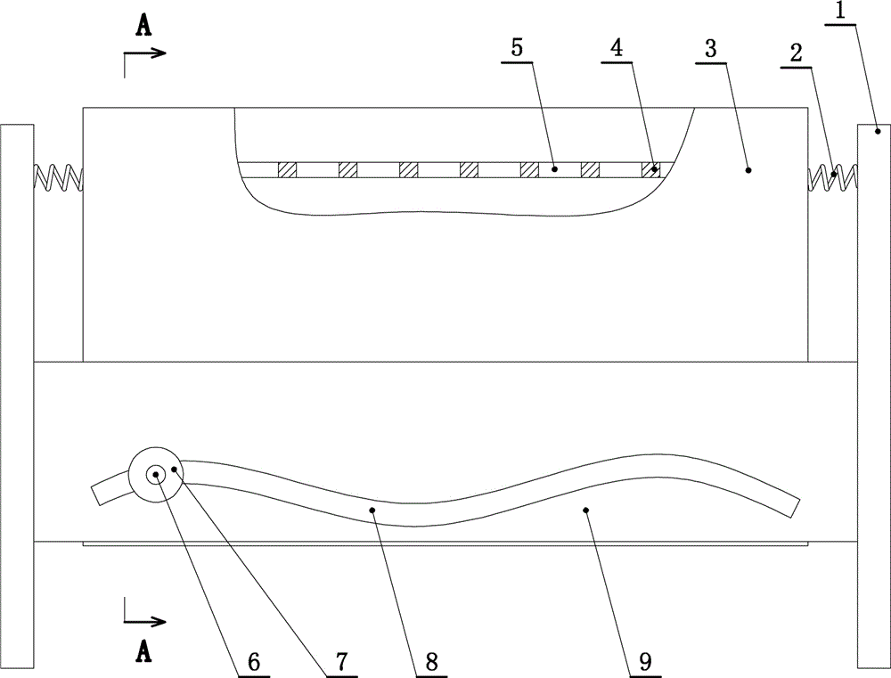
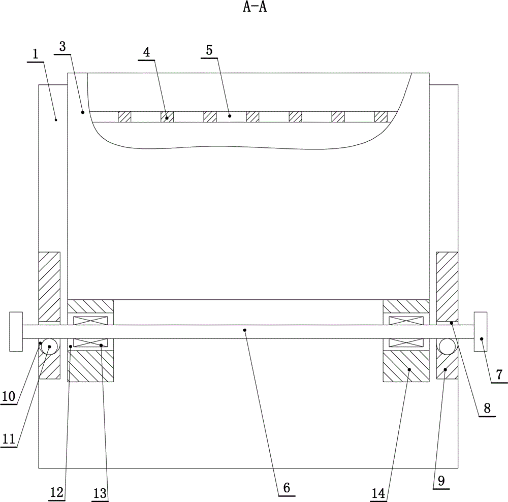
[0020] Such as figure 1 , figure 2 and image 3 As shown, a test tube vibrator includes vertical plates 1 correspondingly arranged at the front and rear, a test tube placement box 3 is fixedly connected between the front and rear two vertical plates 1 through a spring 2, and at least One spring 2 is connected. In this embodiment, three springs 2 are connected between the vertical plate 1 and the test tube placement box 3, two of which are located above and one located below.

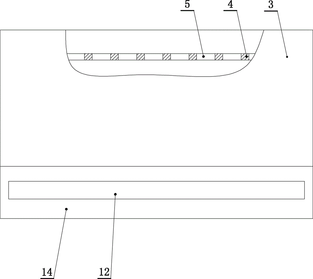
[0021] The test tube placement box 3 is hollow and has an upward opening. The test tube placement box 3 is fixedly connected with a test tube positioning plate 4, and a plurality of test tube perforations 5 are provided on the test tube pos...


PUM


Abstract

A test tube oscillator, a test tube placement box is fixedly connected by springs between the front and rear vertical plates, the test tube placement box is hollow and has an upward opening, a test tube positioning plate is fixedly connected to the test tube positioning box, and a test tube positioning plate is set There are multiple test tube perforations; the two vertical plates on the left and right sides of the test tube storage box are respectively fixedly connected with left and right corresponding baffles, and each baffle is provided with horizontal push grooves, and the push grooves are wavy. A push rod is plugged in the left and right push grooves, and the test tube placement box is erected on the push rod. A support plate is fixedly connected to the bottom of the test tube placement box, and the support plate is provided with a support groove along its length direction, and the push rod passes through the support groove. The outer transmission of the push rod in the support groove is connected with an inner bearing. Two support plates are fixedly connected to the bottom of the test tube placement box, and the push rod passes through the left and right support grooves. The lower side wall of the push groove is recessed downwards and provided with a plurality of connected pits, balls are rollingly arranged in the pits, and the push rod is in rolling contact with the balls.

Description

technical field [0001] The invention relates to a medical device, in particular to a test tube oscillator. Background technique [0002] In medical practice, vibration operation is required in many cases, for example, inspectors oscillate samples, nurses oscillate after mixing solid medicine and liquid medicine, etc. Some of the current oscillating operations adopt the direct shaking of the test tube by hand, which is not only troublesome, but also has a bad oscillation effect. In order to obtain a better oscillation effect, some hospitals purchase special oscillators, but the structures are complex and the cost is high. Contents of the invention [0003] The invention aims at the deficiencies and provides a test tube oscillator with simple structure, low price and good use effect. [0004] The technical scheme that the present invention solves the problems of the technologies described above is as follows: [0005] A test tube vibrator, including front and rear vertica...

Claims


Application Information

Patent Timeline
Patent Type & Authority Patents(China)
IPC IPC(8): B01F11/00
CPCB01F31/20B01F31/201B01F31/26B01F31/24B01F31/70B01F2101/2202B01F2101/23B01F2101/22
Inventor 于红艳
Owner 于红艳
Why Eureka
Try Eureka