Motor vehicle driven by hybrid power

A motor vehicle and hybrid technology, which is applied in the direction of hybrid vehicles, motor vehicles, electric vehicles, etc., and can solve the problem of delay in the effect of the pressure reducing valve device

Inactive Publication Date: 2016-06-01
DR ING H C F PORSCHE AG
View PDF6 Cites 1 Cited by
  • Summary
  • Abstract
  • Description
  • Claims
  • Application Information

AI Technical Summary

Problems solved by technology

However, this known solution has the disadvantage that it can only be applied to brake systems with a balance beam system and due t

Method used


Image

  • Motor vehicle driven by hybrid power
  • Motor vehicle driven by hybrid power
  • Motor vehicle driven by hybrid power

Examples


Embodiment Construction

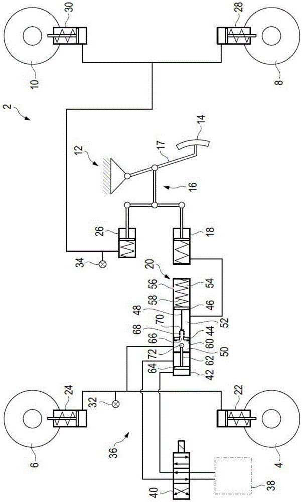
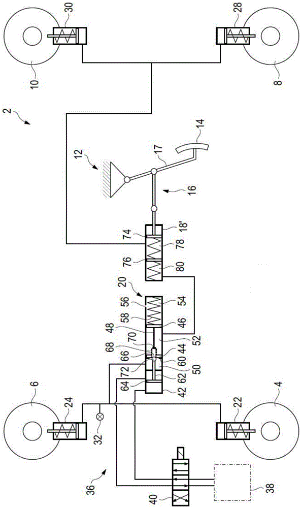
[0015] figure 1 The motor vehicle 2 is shown in the form of a hydraulic circuit diagram. Two front wheels 4, 6 are provided on a front axle (not further shown). The rear wheels 8 , 10 are correspondingly arranged on a rear axle (not shown further). Motor vehicle 2 may also be referred to as a hybrid vehicle and has an electric machine (not further shown) operatively connected to the front axle and has an internal combustion engine (not further shown) operatively connected to the rear axle. It should be clear that there are a large number of so-called hybrid drives, all of which fall within the scope of protection of the present invention.

[0016] In this context, the electric machine performs the role of an electric motor on the one hand when the wheels 4 , 6 of the front axle are driven by the electric machine. Furthermore, in the recuperation phase in which the electric machine acts as a generator, said electric machine can convert both quantities of braking energy gene...


PUM


Abstract

A motor vehicle driven by hybrid power is provided with: a recovery device which allows recovery of energy in a brake process; a brake system having a pedal, a main brake cylinder and a wheel brake, the wheel brake being actuated based on pedal motion and a moving fluid of a piston in the main brake cylinder; a reducing valve device which reduces brake pressure in a recovery stage; a compensator used for compensating the reducing valve device; and at least another main brake cylinder, a first piston and a second piston being mutually connected via a first connecting element and dividing the main brake cylinder into at least three chambers, at least the first chamber and the second chamber being designed to be hydraulic chambers, the third chamber having a compensating element and a compensator having a return function, the first piston having a cut-through opening for fluid connection of the first chamber to the second chamber, and the first piston being connected to a piston of a hydraulic actuator of the reducing valve device through a second connecting element in a direction opposite to a brake direction and being closable; and a stop element used for the first piston or second piston, the main brake cylinder also executing a pressure adjustment function.

Description


Claims


Application Information

Patent Timeline
Owner DR ING H C F PORSCHE AG
Why Eureka
Try Eureka