Quenching inductor for threaded surface of shaft disc type parts

A technology of quenching inductors and threaded surfaces, applied in the direction of quenching devices, furnace types, furnaces, etc., can solve the problems of complex installation and replacement of inductors, increase the overall investment of quenching equipment, uneven heating or cooling, etc., and achieve simple and reasonable structure , Firm and reliable fixation, convenient installation and replacement

Active Publication Date: 2016-06-01
SHIYAN HENGJIN INDUCTION TECH CO LTD
View PDF4 Cites 3 Cited by
  • Summary
  • Abstract
  • Description
  • Claims
  • Application Information

AI Technical Summary

Problems solved by technology

At present, most of the existing similar inductors are annular or cylindrical structures, which can better achieve the purpose of induction hardening when the length is large and the diameter is small; but when the diameter of the workpiece is small, the length is short and mass production is rapid During processing, the installation and replacement process of the inductor is complicated, especially the quenching treatment of irregular surfaces such as threaded surfaces, which will cause uneven heating or cooling, resulting in reduced processing quality, although the use of new induction heating technology can reduce such Defects, but greatly increased the overall investment in quenching equipment, increased production costs, and could not eradicate related disadvantages

Method used


Image

  • Quenching inductor for threaded surface of shaft disc type parts
  • Quenching inductor for threaded surface of shaft disc type parts
  • Quenching inductor for threaded surface of shaft disc type parts

Examples


Embodiment Construction

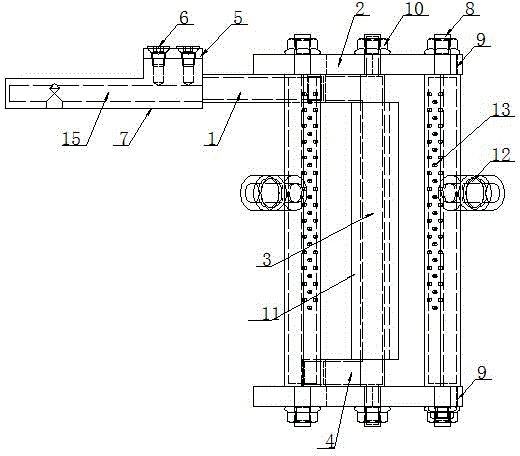
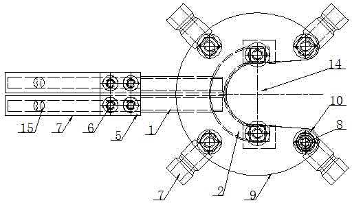
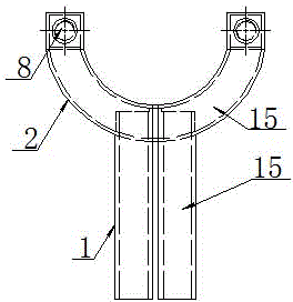
[0017] Such as figure 1 , figure 2 , image 3 and Figure 4 As shown, a quenching inductor for the threaded surface of shaft-disk parts, the quenching inductor is mainly composed of an induction coil, a sprinkler, a magnetizer, a coil fixing plate and a sprinkler fixing plate; the induction coil is composed of a first connecting pipe 1 , the first connecting ring 2, the effective ring 3 and the second connecting ring 4, one end of a pair of first connecting pipes 1 arranged in parallel at intervals is connected to one end of the second connecting pipe 7 through a coil fixing plate 5 and a bolt 6, the second The other end of the second connecting pipe 7 is connected to the quenching equipment through the quick-change joint on the quenching equipment; the other end of the first connecting pipe 1 is connected to the two ends of the second connecting ring 4 through the first connecting ring 2 and the effective ring 3 in turn to form a circuit The induction coil, the first conn...


PUM


Abstract

The invention provides a quenching inductor for the threaded surfaces of shaft disc type parts. The quenching inductor is mainly composed of an induction coil, a sprinkler, magnetizers and sprinkler fixing plates. The induction coil is a loop induction coil composed of first connecting pipes, a first connecting ring, effective coils and a second connecting ring. A second connecting pipe communicates with an inner hole of the induction coil to form a loop coolant channel. The effective coils are symmetrically distributed along the two sides of the axis of the threaded surface of a workpiece and fixed between the symmetrically arranged sprinkler fixing plates through studs and nuts, and the studs and the nuts are arranged on the end faces of the effective coils. Each magnetizer is fixed to the corresponding effective coil in a clamped mode. The sprinkler is composed of sprinkler heads and quickly-changed water nozzles. The sprinkler heads are fixed between the symmetrically arranged sprinkler fixing plates through studs and nuts, and the studs and the nuts are arranged on the end faces of the sprinkler heads. Sprinkler holes are distributed in the face, corresponding to the induction coil, of each sprinkler head. Each sprinkler fixing plate is provided with a workpiece guide opening. According to the quenching inductor for the threaded surfaces of the shaft disc type parts, the structure is simple and reasonable, all the components are connected with one another to form a whole, installing and replacing are convenient and fast, and rapid induction quenching of the kind of workpieces is achieved.

Description

technical field [0001] The invention relates to an induction heating device, in particular to a quenching inductor for the threaded surface of shaft and disk parts. Background technique [0002] The shaft-disc workpiece generates high temperature on the surface of the workpiece or at a certain depth on the surface through electromagnetic induction to heat the part of the workpiece in a short period of time, and then the workpiece is cooled rapidly by the coolant sprayed by the water sprayer to complete the quenching processing task. At present, most of the existing similar inductors are annular or cylindrical structures, which can better achieve the purpose of induction hardening when the length is large and the diameter is small; but when the diameter of the workpiece is small, the length is short and mass production is rapid During processing, the installation and replacement process of the inductor is complicated, especially the quenching treatment of irregular surfaces s...

Claims


Application Information

Patent Timeline
IPC IPC(8): C21D1/667C21D1/42C21D9/00
CPCY02P10/25
Inventor 周祥成万美华
Owner SHIYAN HENGJIN INDUCTION TECH CO LTD
Why Eureka
Try Eureka