
Turbine blade with uneven cooling intensity in radial direction

A technology for cooling strength and turbine blades, applied to blade support components, engine components, machines/engines, etc., can solve the problems of increasing the probability of safety problems, increasing engine danger, energy consumption and waste, and achieving the goal of not easily wasting energy , Increased cooling air volume, high safety effect

Inactive Publication Date: 2016-06-01
AECC SHENYANG ENGINE RES INST
View PDF7 Cites 2 Cited by
  • Summary
  • Abstract
  • Description
  • Claims
  • Application Information

AI Technical Summary

Problems solved by technology

In this way, when the temperature field at the outlet of the main combustion chamber is not uniform, there is excessive cooling in the low-temperature area of ​​the blade tip and blade root, resulting in waste of energy consumption, and insufficient cooling in the high-temperature area in the middle, resulting in ablation. , increasing the danger of the engine running, increasing the probability of safety problems

Method used


Image

  • Turbine blade with uneven cooling intensity in radial direction
  • Turbine blade with uneven cooling intensity in radial direction

Examples


Embodiment Construction

[0017] In order to make the objectives, technical solutions and advantages of the present invention clearer, the technical solutions in the embodiments of the present invention will be described in more detail below in conjunction with the drawings in the embodiments of the present invention. In the drawings, the same or similar reference numerals denote the same or similar elements or elements having the same or similar functions throughout. The described embodiments are some, but not all, embodiments of the invention. The embodiments described below by referring to the figures are exemplary and are intended to explain the present invention and should not be construed as limiting the present invention. Based on the embodiments of the present invention, all other embodiments obtained by persons of ordinary skill in the art without creative efforts fall within the protection scope of the present invention. Embodiments of the present invention will be described in detail below ...


PUM


Abstract

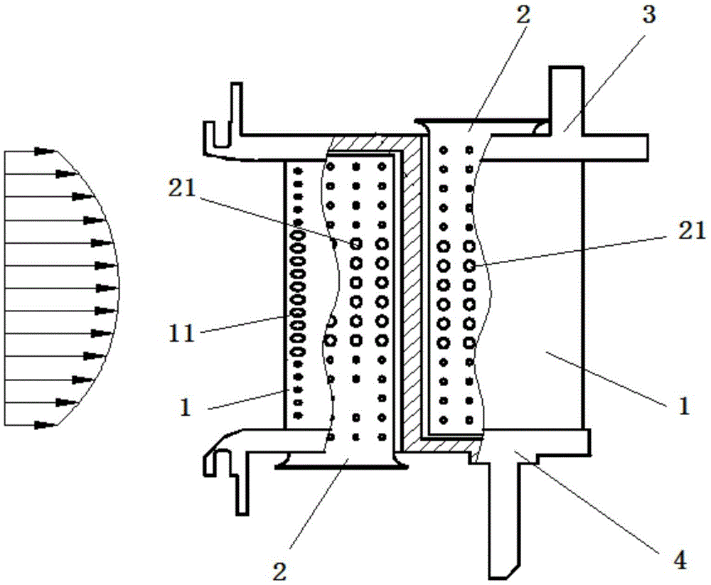
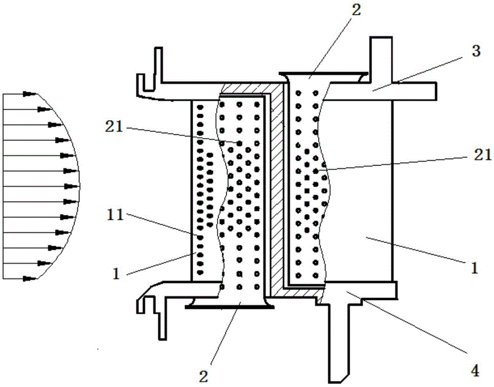
The invention relates to cooling design for a turbine of an aircraft engine, in particular to a turbine blade with uneven cooling intensity in a radial direction. The turbine blade comprises blade bodies and cold air conduits, wherein a cooling cavity is formed in each of the blade bodies, a plurality of air film holes communicating with the cooling cavities are formed in the outer wall of each of the blade bodies, and the sizes and the arrangement positions of the gas film holes are matched with preset parameters of fuel gas; the cold air conduits are arranged in the cooling cavities, and cooling holes of which the number and the positions correspond to those of the air film holes in the blade bodies are formed in the cold air conduits. According to the turbine blade with uneven cooling intensity in the radial direction, disclosed by the invention, the flow of cooling air at the middle parts of the blade bodies can be increased, the flow of the cooling air at two ends of the blade bodies is reduced, the temperature of the whole blade bodies is even, the waste of energy sources is not liable to cause, an ablation phenomenon is also not liable to generate, and the safety is high.

Description

technical field [0001] The invention relates to the cooling design of an aero-engine turbine, in particular to a turbine blade with radially non-uniform cooling intensity. Background technique [0002] For aero-engine turbines, the current blades adopt a radially uniform design of cooling intensity, that is, the cooling structure and the amount of cold air used in the height direction of the blades are the same. In this way, when the temperature field at the outlet of the main combustion chamber is not uniform, there is excessive cooling in the low-temperature area of ​​the blade tip and blade root, resulting in waste of energy consumption, and insufficient cooling in the high-temperature area in the middle, resulting in ablation. , The increased risk of engine operation increases the probability of safety issues. Contents of the invention [0003] The object of the present invention is to provide a turbine blade with radially non-uniform cooling intensity, which at least...

Claims


Application Information

Patent Timeline
Patent Type & Authority Applications(China)
IPC IPC(8): F01D5/18
CPCF01D5/186
Inventor 李孝堂吕东
Owner AECC SHENYANG ENGINE RES INST
Learn More