Heat dissipation device special for induction cooker
A technology of a heat sink and an induction cooker, which is applied in the directions of household heating, household heating, electric heating fuel, etc., can solve the problems of low heat dissipation rate and high noise, and achieve the effect of increasing heat dissipation.
- Summary
- Abstract
- Description
- Claims
- Application Information
AI Technical Summary
Problems solved by technology
Method used
Image

Examples
Embodiment Construction
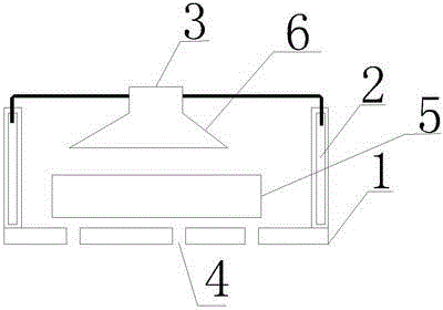
[0017] Such as figure 1 Among them, a special heat dissipation device for an induction cooker includes a casing 1, the outer surface of the side wall of the casing 1 is provided with air holes and water holes, the side wall of the casing 1 is provided with a water channel 2, the material of the upper end surface of the casing 1 is copper sheet, and the edge of the copper sheet is set. In the water channel 2, when working, the water in the water channel 2 can absorb the heat on the copper sheet, and one or more air outlets 3 are provided on the copper sheet, and the material of the lower end surface of the shell 1 is an aluminum alloy plate, and there is one or more air outlets on the aluminum alloy plate. A plurality of air inlets 4 and a fan 5 are arranged inside the housing 1; a wind collecting hood 6 is also provided in the housing, the large opening of the wind collecting hood 6 is aligned with the fan, and the small opening is connected with the air outlet, and the wind co...
PUM
 Abstract
Description
Claims
Application Information
 - Generate Ideas
- Intellectual Property
- Life Sciences
- Materials
- Tech Scout
- Unparalleled Data Quality
- Higher Quality Content
- 60% Fewer Hallucinations
Browse by: Latest US Patents, China's latest patents, Technical Efficacy Thesaurus, Application Domain, Technology Topic, Popular Technical Reports.
© 2025 PatSnap. All rights reserved.Legal|Privacy policy|Modern Slavery Act Transparency Statement|Sitemap|About US| Contact US: help@patsnap.com