
In situ test instrument and method for mechanical, electric, thermal and magnetic coupling material properties under composite load mode

A technology of composite load and material properties, which is applied in the application of repetitive force/pulsation force to test the strength of materials, instruments, and the use of stable tension/pressure to test the strength of materials, etc. It can solve the problem of in-situ testing of material properties.

Active Publication Date: 2018-08-10
JILIN UNIV
View PDF5 Cites 0 Cited by
  • Summary
  • Abstract
  • Description
  • Claims
  • Application Information

AI Technical Summary

Problems solved by technology

[0004] The purpose of the present invention is to provide an in-situ test instrument and method for material properties coupled with force, electricity, heat and magnetism in a composite load mode, so as to solve the problem that existing instruments and equipment cannot realize the in-situ test of material properties under the coupling effect of force-electricity-heat-magnetic multi-physics field The problem

Method used


Image

  • In situ test instrument and method for mechanical, electric, thermal and magnetic coupling material properties under composite load mode
  • In situ test instrument and method for mechanical, electric, thermal and magnetic coupling material properties under composite load mode
  • In situ test instrument and method for mechanical, electric, thermal and magnetic coupling material properties under composite load mode

Examples


Embodiment Construction

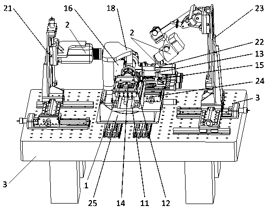
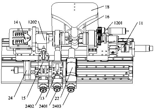
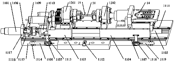
[0046] The detailed content of the present invention and its specific implementation will be further described below in conjunction with the accompanying drawings.

[0047] see Figure 1 to Figure 19 As shown, the in-situ test instrument for the composite load mode electrothermal-magnetic coupling material performance of the present invention includes a composite load-multiphysics field loading test platform 1, an in-situ monitoring platform 2 and a vibration isolation base 3, and the vibration isolation base 3 is used to support composite load-multi-physics field loading test platform 1 and in-situ monitoring platform 2, providing basic installation and positioning for them, and providing effective vibration isolation treatment for the testing process; vibration isolation base 3 provides testing equipment The support of the whole machine and a stable and vibration-free experimental environment, if it is necessary to create a vacuum environment, the core parts such as the comp...


PUM


Abstract

The present invention relates to the field of precision scientific instruments, and provides a material property testing apparatus and method for in situ combined mechanical, electrical, thermal, and magnetic testing in a composite load mode. The apparatus comprises three major portions, a test platform (1) having a composite load and multiple physical fields applied thereto, an in situ monitoring platform (2), and a vibration isolation base (3). The vibration isolation base (3) is mainly used to support the test platform (1) having a composite load and multiple physical fields applied thereto and the in situ monitoring platform (2), position installation thereof, and at the same time, provide effective vibration isolation for precision drive of various loading components, detection components, and in situ monitoring components during tests. By means of precise adjustment of a position and attitude of each monitoring module, the in situ monitoring platform (2) realizes real-time and dynamic in situ monitoring of microscopic deformation, mechanism of damage, changes in microstructure, and property variation of a material sample in the above complex load condition. The present invention has an advantage of a small-size and lightweight structure, and can be optionally provided with a vacuum cavity to accommodate the body of the apparatus, so as to provide a material sample to be tested with a test environment such as a low-pressure environment, a vacuum environment, and an inert gas environment, thus being highly practicable.

Description

technical field [0001] The invention relates to the field of precision scientific instruments, in particular to an in-situ test instrument and method for the performance of a force-electric-thermal-magnetic coupling material in a composite load mode. The in-situ test instrument and method for material microscopic properties under the combined load mode force-electricity-thermal-magnetic multi-physics field coupling loading conditions of the present invention can provide four mechanical loads of "tensile / compressive-low cycle fatigue-torsion-bending" One or more of them can also be used for typical functional materials to carry out microscopic performance tests under the multi-physical field coupling of "stress field-temperature field (high / low temperature)-electric field-magnetic field". Parallel load testing with coexistence of load modes. The in-situ micro-nano indentation test module embedded in the instrument can accurately measure the dynamic evolution of the indentation...

Claims


Application Information

Patent Timeline
Patent Type & Authority Patents(China)
IPC IPC(8): G01N3/00
CPCG01N3/00G01N3/068G01N3/18G01N3/32G01N3/42G01N3/48G01N3/54G01N3/62
Inventor 赵宏伟刘长宜马志超任露泉刘先华周永臣孙霁雯乔元森任壮洪坤张富范尊强张志辉呼咏董景石
Owner JILIN UNIV
Learn More