
Test system for hydraulic rotary joint

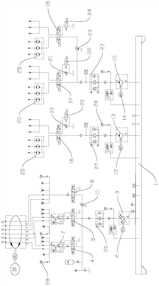
A test system, hydraulic rotation technology, applied in the field of hydraulic systems, can solve the problems that customers cannot meet other performance requirements of products, single test leakage or torque, and the result parameters are not rich enough, so as to meet the requirements of multi-performance products, test Accurate results and rich workpiece performance parameters

Pending Publication Date: 2021-02-05
郎溪腾旋科技有限公司
View PDF0 Cites 0 Cited by
  • Summary
  • Abstract
  • Description
  • Claims
  • Application Information

AI Technical Summary

Problems solved by technology

[0004] The technical problem to be solved by the present invention is: the performance of the existing hydraulic test system is relatively simple, and it can only test some leakage or torque. The problem of requirement, the present invention provides a kind of testing system of hydraulic rotary joint to solve the above-mentioned problem

Method used


Image

  • Test system for hydraulic rotary joint
  • Test system for hydraulic rotary joint

Examples


Embodiment Construction

[0024] Embodiments of the present invention are described in detail below, examples of which are shown in the drawings, wherein the same or similar reference numerals designate the same or similar elements or elements having the same or similar functions throughout. The embodiments described below by referring to the figures are exemplary only for explaining the present invention and should not be construed as limiting the present invention. On the contrary, the embodiments of the present invention include all changes, modifications and equivalents coming within the spirit and scope of the appended claims.

[0025] In describing the present invention, it should be understood that the terms "center", "longitudinal", "transverse", "length", "width", "thickness", "upper", "lower", "front", " Back", "Left", "Right", "Vertical", "Horizontal", "Top", "Bottom", "Inner", "Outer", "Axial", "Radial", "Circumferential", etc. The indicated orientation or positional relationship is based ...


PUM


Abstract

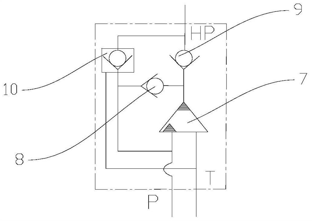
The invention provides a test system for a hydraulic rotary joint. The test system comprises an oil tank, a pulse test system, a pressure maintaining test system and a tested workpiece, and the pulsetest system is internally provided with a first energy output oil path, a first control oil path, a pressurizing oil path and a workpiece which are connected in sequence; and a second energy input oilway, a second control oil way and a workpiece are sequentially connected in the pressure maintaining test system. The transient performance and the steady-state performance of the workpiece can be tested respectively through the arranged pulse test system and the pressure maintaining test system, obtained workpiece performance parameters are rich, the requirements of customers for product diversity performance can be met, and in addition, the test system is relatively precise in structural design, stable in work and accurate in test result.

Description

technical field [0001] The invention relates to a hydraulic system, in particular to a testing system for a hydraulic rotary joint. Background technique [0002] After the development of hydraulic testing technology in the past 10 years, it has gradually transitioned from traditional steady-state testing, which only satisfies some necessary working stress and environmental stress simulation, to focusing on dynamic performance, microscopic characteristics and system matching performance. The test equipment has gradually transitioned from manual operation and secondary instruments to a computer-based measurement and control center, with complex system technology for data processing and analysis. [0003] Hydraulic rotary joints are the core components of construction machinery, and their performance and reliability parameters directly affect the use of the whole machine. However, the existing test system has a relatively single test performance and can only test some leaks. O...

Claims


Application Information

Patent Timeline
Patent Type & Authority Applications(China)
IPC IPC(8): F15B11/032F15B13/02F15B3/00G01M13/00
CPCF15B3/00F15B11/032F15B13/02F15B2013/002F15B2211/20515F15B2211/20576G01M13/00
Inventor 曹寿林徐回李筱凡牛艳琴王勃
Owner 郎溪腾旋科技有限公司
Learn More