
An automatic wiring system for an intelligent control cabinet

A technology of intelligent control cabinet and automatic wiring, applied in connection, circuit/collector parts, connection and connection completed by deformation, etc., can solve problems such as low debugging efficiency, and achieve the effect of solving low debugging efficiency and high work efficiency

Active Publication Date: 2019-08-23
GREE ELECTRIC APPLIANCES INC
View PDF6 Cites 0 Cited by
  • Summary
  • Abstract
  • Description
  • Claims
  • Application Information

AI Technical Summary

Problems solved by technology

[0003] In view of this, this application provides an automatic wiring system for intelligent control cabinets, which is used for automatic wiring of the terminal blocks of intelligent control cabinets, so as to solve the problem of low debugging efficiency caused by manual wiring

Method used


Image

  • An automatic wiring system for an intelligent control cabinet
  • An automatic wiring system for an intelligent control cabinet
  • An automatic wiring system for an intelligent control cabinet

Examples


Embodiment 1

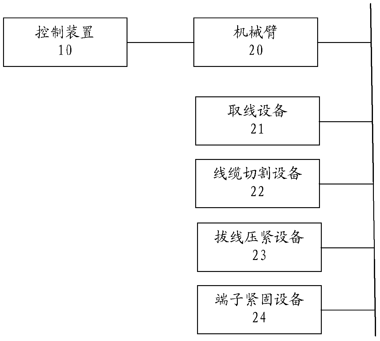
[0031] figure 1 It is a schematic diagram of an automatic wiring system for an intelligent control cabinet provided in an embodiment of the present application.

[0032] Such as figure 1 As shown, the automatic wiring system of the intelligent control cabinet provided by the present application includes a control device 10 and a robot arm 20 , and the control device 10 is connected to the robot arm 20 for controlling the robot arm 20 .

[0033] A plurality of devices are disposed on the mechanical arm 20 , including a wire taking device 21 , a cable cutting device 22 , a wire pulling and pressing device 23 and a terminal fastening device 24 .

[0034] The control device 10 stores connection parameters of the intelligent control cabinet, and the connection parameters include terminal positions and terminal numbers of the connection terminals of the intelligent control cabinet. When performing wiring operations on the intelligent control cabinet, the control device outputs mot...

Embodiment 2

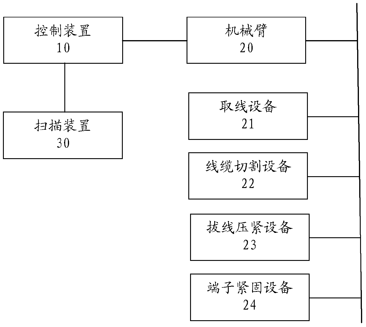
[0044] figure 2 It is a schematic diagram of an automatic wiring system for an intelligent control cabinet provided in another embodiment of the present application.

[0045] Such as figure 2 As shown, the automatic wiring system provided in this embodiment is based on the previous embodiment with an additional input device 60, which is connected to the control device.

[0046] Operators can use the input device 60 to input drawings containing wiring parameters into the control device, so that the system can meet the wiring tasks of different types of intelligent control cabinets.


PUM


Abstract

The application provides an automatic wiring system of an intelligent control cabinet. The system comprises a control device and a mechanical arm, wherein the mechanical arm is provided with a wire taking device, a cable cutting device, a wire-pulling pressing device and a terminal fastening device, the control device is used for storing a wiring parameter of the intelligent control cabinet and outputting a motion instruction, a taking instruction, a cutting instruction, a wire-pulling pressing instruction and a fixing instruction according to the wiring parameter, the wire taking device is used for taking a cable to be connected from an incoming line groove according to the taking instruction and transferring the cable to a wiring terminal corresponding to the wiring parameter, the cable cutting device is used for carrying out cutting operation on the end part of the cable according to the cutting instruction, the wire-pulling pressing device is used for wire pulling operation on the end part of the cable according to the wire-pulling instruction and pressing the end part of the cable subjected to wire pulling into the wiring terminal, and the terminal fastening device is used for fastening a bolt of the wiring terminal according to the fixing instruction. By the system, the problem of relatively low debugging efficiency caused by manual wiring can be solved.

Description

technical field [0001] The present application relates to the technical field of automatic control, and more specifically, relates to an automatic wiring system of an intelligent control cabinet. Background technique [0002] Intelligent control cabinets are widely used in automatic control places in various fields. There are various electrical equipment for realizing automatic control functions in the intelligent control cabinet, and also include terminal blocks for connecting external devices. In the on-site installation of the intelligent control cabinet, since there is no special wiring equipment, it is necessary to manually wire the terminal block and manually set the code. Due to the large number of wiring in the intelligent control cabinet, the wiring and wiring take up most of the construction period in the project debugging period, resulting in low debugging efficiency. Contents of the invention [0003] In view of this, the present application provides an automa...

Claims


Application Information

Patent Timeline
Patent Type & Authority Patents(China)
IPC IPC(8): H01R43/05H01R43/052
CPCH01R43/05H01R43/052
Inventor 何玉雪章静松杨金龙丁文涛姜春苗刘纯王聪钟兴宁成智华黄俊睿马书明
Owner GREE ELECTRIC APPLIANCES INC
Learn More