A Commutation Failure Suppression Method Based on Virtual Current Limiter

Active Publication Date: 2018-04-17
NORTH CHINA ELECTRIC POWER UNIV (BAODING)
View PDF1 Cites 0 Cited by
  • Summary
  • Abstract
  • Description
  • Claims
  • Application Information

AI Technical Summary

Problems solved by technology

Therefore, the current VDCOL control lags behind the limitation of the DC current amplitude when the commutation fails on the inverter side, and it is not conducive to preventing continuous commutation failure on the inverter side.

Method used


Image

  • A Commutation Failure Suppression Method Based on Virtual Current Limiter

Examples


Embodiment Construction

[0024] The technical solutions in the embodiments of the present application will be clearly and completely described below in conjunction with the drawings in the embodiments of the present application.

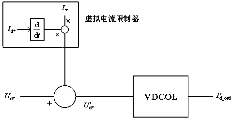
[0025] like figure 1 as shown, figure 1 is the implementation flowchart of the commutation failure suppression method based on the virtual current limiter; in the figure, U d* is the original input VDCOL control voltage value, Δ U * is the voltage drop produced by the DC current on the virtual current limiter, and is the new DC voltage value, L * In order to equivalently convert to the virtual inductance value in the control system, I d* is the DC current equivalently converted to the control system, is the differential operator, and is the current command output by VDCOL under the action of the virtual current limiter.

[0026] The technical solution of the present invention is a commutation failure suppression method based on a DC current limiter, the improvement o...


PUM


Abstract

The invention belongs to the technical field of electric power system transmission, and specifically discloses a commutation failure suppression method based on a virtual current limiter. The virtual current limiter is equivalently connected in series in the traditional DC transmission line. When the DC current on the transmission line increases, the current command is quickly adjusted through the control of the virtual current limiter to achieve the purpose of suppressing the increase of the DC current. The invention is applied to traditional high-voltage direct current transmission, and uses a virtual current limiter to limit the amplitude of direct current overcurrent when a system fails, protect smoothing reactors, thyristors and other devices, and reduce the probability of commutation failure in traditional direct current transmission systems.

Description

technical field [0001] The invention belongs to the technical field of power transmission and distribution, and in particular relates to a commutation failure suppression method based on a virtual current limiter. Background technique [0002] Since the 1950s, the line-commutated-converter High Voltage Direct Current (LCC-HVDC) of the traditional power grid has gained rapid popularity worldwide due to its characteristics of large-capacity long-distance power transmission and fast controllable active power. develop. [0003] However, since LCC-HVDC uses ordinary thyristors without self-shutoff capability as commutation components, the LCC-HVDC system requires a certain strength of the AC system to achieve commutation, and the commutation voltage needs to be provided by the AC grid. When the power grid fails or the three-phase is seriously asymmetrical, the AC bus voltage will drop, the line voltage zero crossing point may be advanced, the commutation overlap angle of the LCC...

Claims


Application Information

Patent Timeline
Patent Type & Authority Patents(China)
IPC IPC(8): H02J1/00
Inventor 郭春义赵成勇刘羽超张帆刘炜
Owner NORTH CHINA ELECTRIC POWER UNIV (BAODING)
Why Eureka
Try Eureka