Method for measuring torque applied by a driver on a pedal of an electric bicycle and electric bicycle

A technology for electric bicycles, drivers, applied in the direction of measuring force, measuring device, torque measurement, etc.

Active Publication Date: 2019-02-01
VTESCO TECH GMBH
View PDF10 Cites 0 Cited by
  • Summary
  • Abstract
  • Description
  • Claims
  • Application Information

AI Technical Summary

Problems solved by technology

Then this has disadvantages regarding the quantitativeness of the assist and the reaction time

Method used


Image

  • Method for measuring torque applied by a driver on a pedal of an electric bicycle and electric bicycle
  • Method for measuring torque applied by a driver on a pedal of an electric bicycle and electric bicycle

Examples


Embodiment Construction

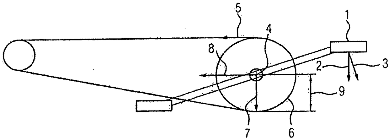
[0030] for in figure 1 For example, a pedal position with a vertically applied pedal force is shown for the chain drive of a bicycle shown schematically in FIG. Force 2 is applied via pedal 1 (shown as a vector). This force 2 has a force component 3 which exerts a torque on the pedal shaft 4 . This torque results in a chain force 5 which increases the ratio of the crankshaft length to the radius of the ring gear 6 compared to the force component 3 . Forces 2 and 5 are supported in the pedal bearings and here result in force 7 , which runs vertically downwards and contains no information about the torque, and force 8 , which is multiplied by ring gear radius 9 , yields torque because force 8 is equivalent to force 5. The torque exerted by the driver can thus be determined by measuring the force 8 .

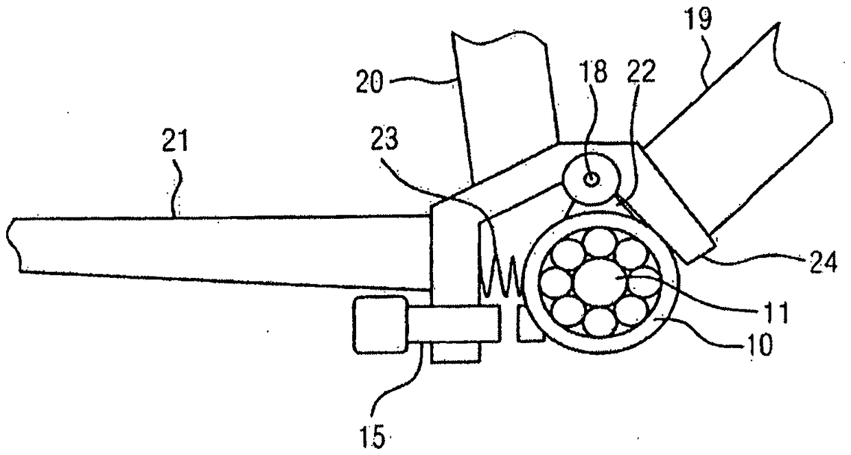
[0031] figure 2 shows an embodiment of the pedal bearing in vertical section. In this embodiment, the pedal bearing 10 is eccentrically and rotatably suspended on a short ro...


PUM


Abstract

The invention relates to a method for measuring the torque exerted by the driver on the pedal of an electric bicycle, in which the force acting on the chain of the bicycle is measured by measuring the elastic deformation or deflection of the fastening part of the pedal bearing. The shift is acquired and the applied torque is determined therefrom. In order to provide a method of the type described in the text, which measures the deformation or deflection of the elastic sleeve as the pedal bearing fastening, the method can be implemented in a simple manner with particularly simple components.

Description

technical field [0001] The invention relates to a method for measuring the torque exerted by the driver on the pedals of an electric bicycle. Background technique [0002] Optimal control of the electric drive is expedient for such electric bicycles (bicycles with an electric drive). In this respect, the signal of the sensor can be used to measure the torque, which is applied by the driver via the pedal. [0003] Known here are torque sensors which measure the tension of the axle via which the pedal transmits torque to the front sprocket. Since a self-rotating shaft is involved here, the measuring principle must be contactless and independent of rotation. The applied principle requires special shafts which are either produced from magnetically suitable metals or are suitably coated. Furthermore, expensive coils and electrical signal processing are required for magnetic measurements. [0004] In a cost-effective solution, the support is controlled by the electric motor vi...

Claims


Application Information

Patent Timeline
Patent Type & Authority Patents(China)
IPC IPC(8): B62M6/50G01L3/10
CPCB62M6/50G01L3/108G01L1/246B60L50/20B62J45/411B62J45/421
Inventor M.魏格尔
Owner VTESCO TECH GMBH
Why Eureka
Try Eureka