Molded stator, molded electric motor, and air conditioner

A technology for molded stators and stators, which is applied in the fields of molded motors, air conditioners, and molded stators, and can solve problems such as difficult detection of rotor positions and motor inoperability

Inactive Publication Date: 2016-06-01
MITSUBISHI ELECTRIC CORP
View PDF7 Cites 2 Cited by
  • Summary
  • Abstract
  • Description
  • Claims
  • Application Information

AI Technical Summary

Problems solved by technology

Therefore, there is a problem that it is difficult to detect the rotor position, which may cause the motor to fail to operate.

Method used


Image

  • Molded stator, molded electric motor, and air conditioner
  • Molded stator, molded electric motor, and air conditioner
  • Molded stator, molded electric motor, and air conditioner

Examples


Embodiment approach

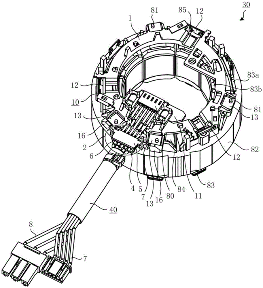
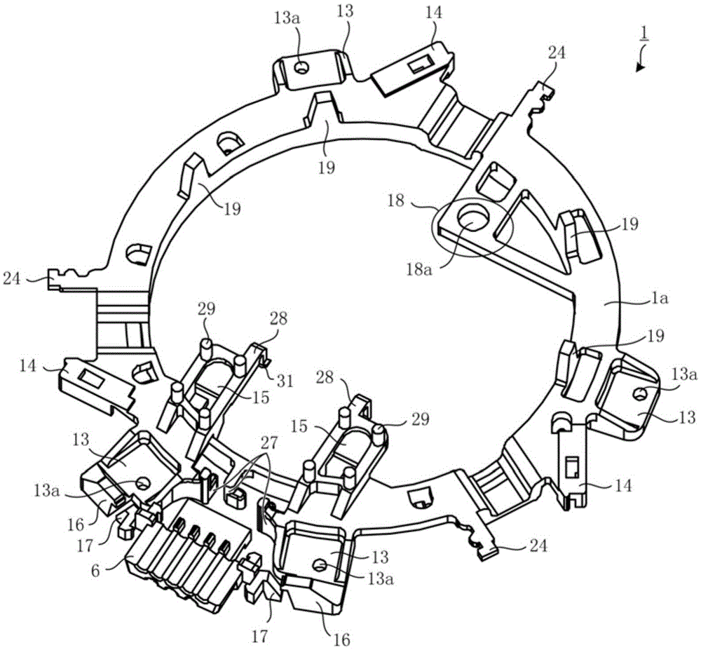
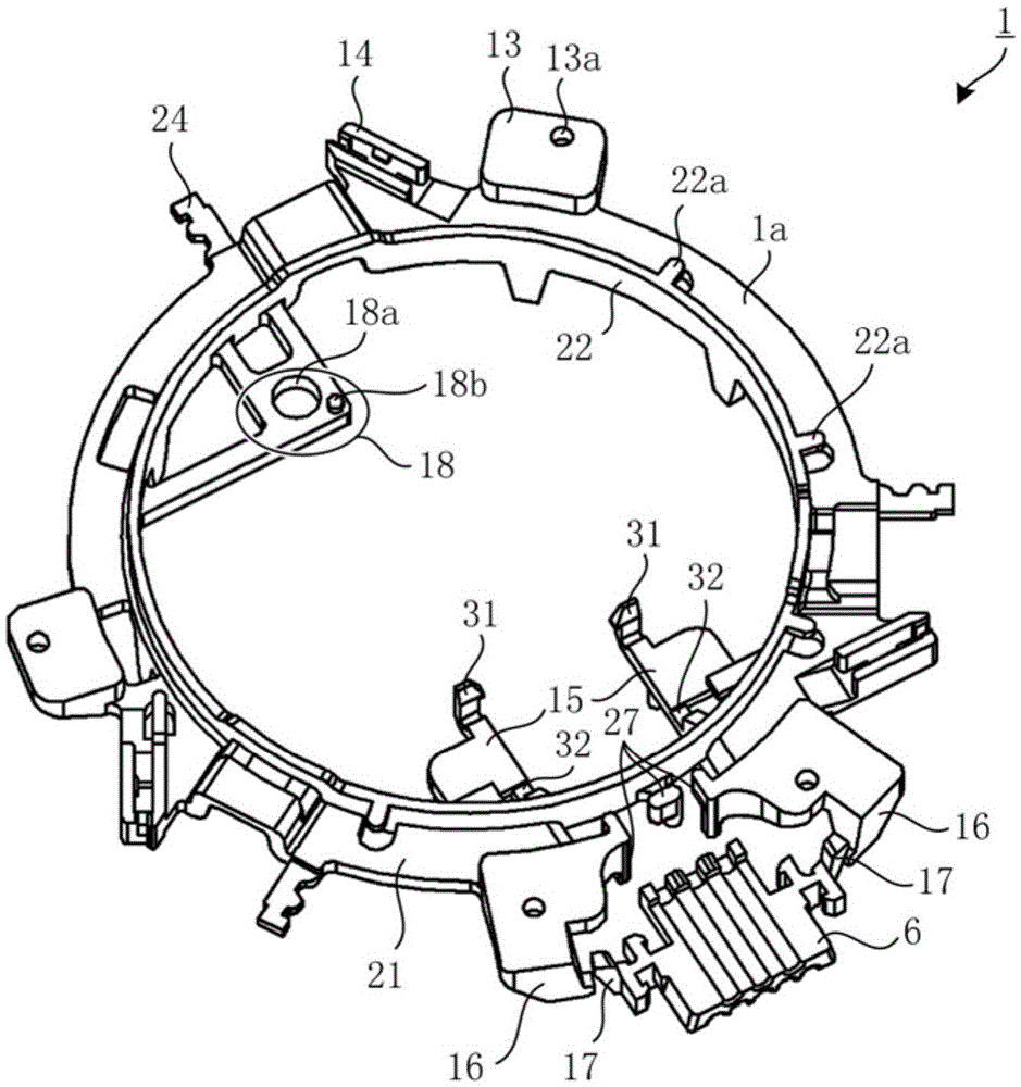
[0085] figure 1 It is a perspective view looking at the stator assembly of the electric motor concerning embodiment of this invention from the board|substrate side. figure 2 yes figure 1 A perspective view of the lead wiring assembly shown. image 3 It is viewed from the back (other side) figure 2 Perspective view of the wiring components shown. Figure 4 yes figure 2 An enlarged view of the lead wire terminal holding part of the lead wire wiring component shown. Figure 5 yes figure 2 This is an enlarged view of the lead-out member included in the lead wire wiring member and its surroundings. Image 6 yes figure 2 An enlarged view of the substrate holding portion and its surroundings included in the lead wiring component shown. Figure 7 is from with Image 6 An enlarged view of the substrate holder and its surroundings viewed from different directions. Figure 8 is a perspective view of the sensor substrate. Figure 9 It is a perspective view of the lead wire w...


PUM


Abstract

A molded stator of the present invention includes a stator and a substrate on which a rotor position detection circuit is mounted and has an outer casing formed of a molded resin. The molded stator comprises: a doughnut-shaped lead-wire wiring component (1) that is attached to one axial-direction end of the stator and wires a power supply lead-wire up to a stator winding and a sensor lead-wire up to the position detection circuit; a bush component (6) that is provided on the radial outside of the lead-wire wiring component (1) and leads the power supply lead-wire and the sensor lead-wire to the outside of the molded stator; a power supply lead-wire holding component that is mounted on the bush component (6) and holds the power supply lead-wire; and a sensor lead-wire holding component that is mounted on the bush component (6) and holds the sensor lead-wire. The bush component (6) is connected to a locking portion (26b) for locking the sensor lead-wire holding component and equipped with a projection (17) on the radial outside, said projection (17) being a planar portion that is substantially vertical to the radial direction of the stator.

Description

technical field [0001] The present invention relates to a molded stator, a molded motor and an air conditioner. Background technique [0002] Conventionally, molded motors have been used as fan motors for indoor units and fan motors for outdoor units of air conditioners. In this molded motor, the stator is molded from a molding resin to form an outer shell, and the rotor is freely arranged on the inner peripheral side of the outer shell. A wire lead-out part is attached to the molded motor to lead out the lead wires from the stator or the wiring board to the outside. Furthermore, the wiring lead-out member is integrally molded with a molded resin together with the stator and the wiring member. [0003] However, with such a structure, water tends to infiltrate from the gap or interface between the outer shell of the molded motor and the wire lead-out member or from the gap or interface between the wire lead-out member and the lead wire. Therefore, there has been a problem ...

Claims


Application Information

Patent Timeline
Patent Type & Authority Applications(China)
IPC IPC(8): H02K29/08H02K3/52H02K5/22H02K11/21
CPCH02K29/08H02K3/522H02K11/21H02K5/225F25D17/06H02K5/02H02K15/02H02K15/08
Inventor 浦边优人麻生洋树坂乃边和宪山本峰雄石井博幸尾屋隼一郎
Owner MITSUBISHI ELECTRIC CORP
Why Eureka
Try Eureka