Synchronization in a beamforming system

A technology of beamforming and beam, which is applied in the field of control signaling transmission and synchronization, and can solve problems such as not considering space synchronization

Active Publication Date: 2016-06-01
MEDIATEK INC
View PDF3 Cites 41 Cited by
  • Summary
  • Abstract
  • Description
  • Claims
  • Application Information

AI Technical Summary

Problems solved by technology

Three pilot signals for time-frequency synchronization and channel estimation introduce too much

Method used


Image

  • Synchronization in a beamforming system
  • Synchronization in a beamforming system
  • Synchronization in a beamforming system

Examples


Embodiment Construction

[0052] Some embodiments of the invention will now be described in detail, some examples of which are illustrated in the accompanying drawings.

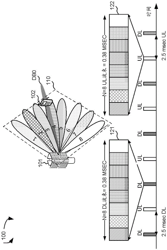
[0053] figure 1 is a schematic diagram of a control beam (Control Beam, CB) in a beamforming mmWave cellular network 100 according to one novel aspect. The beamforming network 100 includes a base station (BaseStation, BS) 101 and a user equipment (UserEquipment, UE) 102 . mmWave cellular networks use narrow beams for directional communications and can support multi-gigabit data rates. Directional communication may be accomplished by digital and / or analog beamforming, where multiple sets of beamforming weights are applied to multiple antenna elements to form multiple beams. For control purposes, a coarse set of TX / RX control beams is provided by the base station in the cellular system. The set of control beams may be configured periodically, or occur indefinitely and repeat in an order known to the UE. The set of control beams cov...


PUM


Abstract

A beamforming system synchronization architecture is proposed to allow a receiving device to synchronize to a transmitting device in time, frequency, and spatial domain in the most challenging situation with very high pathloss. A periodically configured time-frequency resource blocks in which the transmitting device uses the same beamforming weights for its control beam transmission to the receiving device. A pilot signal for each of the control beams is transmitted in each of the periodically configured time-frequency resource blocks. The same synchronization signal can be used for all stages of synchronization including initial coarse synchronization, device and beam identification, and channel estimation for data demodulation.

Description

[0001] cross reference [0002] This application claims priority under 35 U.S.C. §119 to U.S. Provisional Application 62 / 054,485, filed September 24, 2014, titled "Control Signalingina Beamforming System," and U.S. Provisional Application 62 / 054,488, entitled "Synchronization ina Beamforming System," and the above application is incorporated by reference. technical field [0003] The present invention relates to wireless communications, and more particularly to control signaling and synchronization in millimeter wave (mmW) beamforming systems. Background technique [0004] The increasing shortage of mobile carrier bandwidth in next-generation broadband cellular communication networks has facilitated the exploration of the underutilized mmW spectrum between 3G and 300 GHz. The available spectrum in mmW bands is two hundred times larger than that of traditional cellular systems. mmW wireless networks use narrow beams for directional communications and can support multi-gig...

Claims


Application Information

Patent Timeline
IPC IPC(8): H04W56/00
CPCH04L27/2607H04L27/2628H04L27/2655H04B7/0617H04L5/0023H04L5/005H04L27/26132H04J11/0079H04J2011/0096
Inventor 桂建卿苏昭诚陈儒雅
Owner MEDIATEK INC
Why Eureka
Try Eureka