Reaction tank with catalysis plates

A technology of catalytic plates and reaction tanks, applied in chemical/physical processes, chemical instruments and methods, etc., can solve the problems of time-consuming, labor-intensive, hindered reaction, waste of manpower and material resources, etc., and achieve the goal of avoiding recycling, fast reaction speed and high production efficiency Effect

Inactive Publication Date: 2016-06-08
天津渤海晟机械设备配件有限公司
View PDF0 Cites 0 Cited by
  • Summary
  • Abstract
  • Description
  • Claims
  • Application Information

AI Technical Summary

Problems solved by technology

[0002] The reaction tank is the most used reaction equipment in the field of petrochemical industry. Most of the existing reaction tanks use a stirring device to stir the materials evenly and accelerate the reaction. However, a large amount of heat is also generated during the stirring, which will hinder the reaction for low-temperature reactions. At the same time, for reactions where the catalyst can be recycled, if the catalyst is used and then filtered and recovered, it will waste manpower and material resources. Fixing the catalyst on the catalytic plate will save a lot of work steps. In addition, in order to monitor the progress of the reaction, it is necessary to A part of the sample is taken out of the reaction tank for detection. If the material is taken directly from the tank, it will take time and effort. A reaction tank that can overcome the above shortcomings has not been found yet, and further research and development are needed.

Method used


Image

  • Reaction tank with catalysis plates

Examples


Embodiment Construction

[0011] The present invention will be described in detail below in conjunction with the accompanying drawings.

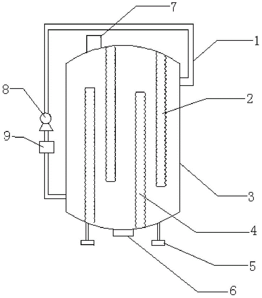
[0012] Such as figure 1 , shown in the structural diagram of the present invention, a kind of reaction tank with catalytic plate of the present invention comprises tank body 3, and the top of described tank body 3 is provided with feed port 7, and the bottom of described tank body 3 is provided with Outlet 6 and support foot 5, the top of described tank body 3 is provided with upper catalytic plate 2, and the bottom of described upper catalytic plate 2 stretches to the bottom of tank body 3 but does not touch the bottom of tank body 3, and described tank body 3 is provided with a lower catalytic plate 4, the top of the lower catalytic plate 4 extends to the top of the tank body 3 but does not touch the top of the tank body 3, the upper catalytic plate 2 and the lower catalytic plate 4 are arranged in a staggered manner, the The surfaces of the upper catalytic plate ...


PUM


Abstract

The present invention provides a reaction tank with catalysis plates. The reaction tank comprises a tank body, wherein the top portion of the tank body is provided with a material inlet, the bottom portion of the tank body is provided with a material outlet and support feet, the top portion of the tank body is provided with upper catalysis plates, the bottom portion of the upper catalysis plate extends to the bottom portion of the tank body and does not contact the bottom portion of the tank body, the bottom portion of the tank body is provided with lower catalysis plates, the top portion of the lower catalysis plate extends to the top portion of the tank body and does not contact the top portion of the tank body, the upper catalysis plates and the lower catalysis plates are arranged in a staggered manner, the surfaces of the upper catalysis plates and the lower catalysis plates are wavy, the outer side of the tank body is provided with a circulation pipe, the inlet of the circulation pipe is positioned on the bottom portion of the tank body, the outlet is positioned on the top portion of the tank body, and the circulation pipe is provided with a sample monitoring chamber and a material sucking pump. According to the present invention, the reaction tank has beneficial effects of simple structure, simple operation, and reaction accelerating.

Description

technical field [0001] The invention belongs to the technical field of petrochemical industry, in particular to a reaction tank with a catalytic plate. Background technique [0002] The reaction tank is the most used reaction equipment in the field of petrochemical industry. Most of the existing reaction tanks use a stirring device to stir the materials evenly and accelerate the reaction. However, a large amount of heat is also generated during the stirring, which will hinder the reaction for low temperature reactions. At the same time, for reactions where the catalyst can be recycled, if the catalyst is used and then filtered and recovered, it will waste manpower and material resources. Fixing the catalyst on the catalytic plate will save a lot of work steps. In addition, in order to monitor the progress of the reaction, it is necessary to A part of the sample is taken out of the reaction tank for detection. If the material is directly taken from the tank, it will be time-c...

Claims


Application Information

Patent Timeline
Patent Type & Authority Applications(China)
IPC IPC(8): B01J8/04
Inventor 王贵军
Owner 天津渤海晟机械设备配件有限公司
Why Eureka
Try Eureka