
Rotating clamp structure

A caliper and rotating shaft technology, which is applied to workpiece clamping devices, manufacturing tools, etc., can solve the problems that the positioning position cannot be fixed, and it is difficult to meet the workpiece positioning requirements.

Inactive Publication Date: 2016-06-08
MT PRECISION MACHINERY MFG
View PDF0 Cites 0 Cited by
  • Summary
  • Abstract
  • Description
  • Claims
  • Application Information

AI Technical Summary

Problems solved by technology

[0002] When the workpiece is inspected, the workpiece must first be clamped and positioned. When clamping and positioning the more complex workpiece, due to the constraints of the positioning of each part of the workpiece, the positioning position of each part cannot be fixed, and the ordinary positioning device The position of the workpiece is relatively fixed, and the positioning position of the workpiece usually meets the positioning requirements of the positioning device. When the position of the positioning device is fixed, it is sometimes difficult to meet the positioning requirements of the workpiece

Method used


Image

  • Rotating clamp structure

Examples


Embodiment Construction

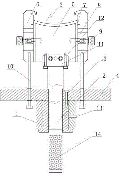
[0008] See figure 1 , a rotary caliper structure, which includes a bushing 1, a rotating shaft 2 is arranged in the bushing 1, a caliper head 3 is arranged on the rotating shaft 2, a support plate 4 is arranged on the rotating shaft 2, and the caliper head 3 includes a positioning block 5 , the positioning block 5 is connected to the rotating shaft 2, L-shaped calipers 6 are arranged on both sides of the positioning block 5, and the calipers 6 are respectively connected to the positioning block 5 through guide rails 7, elongated grooves 8 are respectively arranged on the calipers 6, and elongated grooves 8 are respectively provided with The positioning screw 9 is connected to the positioning block 5 respectively, and the caliper 6 is connected to the support plate 4 through the adjusting bolt 10 respectively. Rotating in the bushing can adjust the clamping position of the caliper on the workpiece, thereby adjusting the positioning position of the workpiece, realizing the chang...


PUM


Abstract

The invention provides a rotating clamp structure. The rotating clamp structure is simple in structure and capable of adjusting the located position of a workpiece to achieve change of the located position of the workpiece and well adapts to a locating demand of the workpiece. The rotating clamp structure comprises a bush, and is characterized in that a rotating shaft is disposed in the bush; a clamp head is disposed on the rotating shaft; supporting plates are mounted on the rotating shaft; the clamp head comprises a locating block which is connected with the rotating shaft; L-shaped clamps are disposed on the two sides of the locating block; the clamps are connected with the locating block through guide ways correspondingly; long grooves are formed in the clamps correspondingly; the long grooves are provided with locating screws correspondingly; the locating screws are connected with the locating block; and the clamps are connected with the supporting plates through adjusting bolts correspondingly.

Description

technical field [0001] The invention relates to the technical field of detection and positioning tools, in particular to a rotary caliper structure. Background technique [0002] When the workpiece is inspected, the workpiece must first be clamped and positioned. When clamping and positioning the more complex workpiece, due to the constraints of the positioning of each part of the workpiece, the positioning position of each part cannot be fixed, and the ordinary positioning device The position of the workpiece is relatively fixed, and the positioning position of the workpiece usually meets the positioning requirements of the positioning device. When the position of the positioning device is fixed, it is sometimes difficult to meet the positioning requirements of the workpiece. Contents of the invention [0003] In view of the above problems, the present invention provides a rotary caliper structure, which has a simple structure, can adjust the positioning position of the w...

Claims


Application Information

Patent Timeline
Patent Type & Authority Applications(China)
IPC IPC(8): B25B11/00
Inventor 蒋新芬
Owner MT PRECISION MACHINERY MFG
Learn More