Multi-direction sequential combined core-pulling device for single slide block of injection mould

A technology for injection molds and core-pulling devices, which is applied in the field of single-slider multi-directional sequentially combined core-pulling devices for injection molds, and can solve problems such as prone to failure, increased mold costs, and complex structures

Inactive Publication Date: 2016-06-08
NINGBO SHUANGLIN MOULD CO LTD
View PDF5 Cites 8 Cited by
  • Summary
  • Abstract
  • Description
  • Claims
  • Application Information

AI Technical Summary

Problems solved by technology

[0003] It is necessary to set multiple core-pulling blocks in different directions at a narrow position and perform sequential core-pulling injection molds, that is, narrow and multi-directional sequential core-pulling injection molds. The existing technology uses multiple oil cylinders to drive each in sequence The core-pulling block action is used for core-pulling and demoulding, and the cost of multiple oil cylinders is high, occupying a large space inside the mold, resulting in increased mold shape, complex structure, and further increase in mold cost; If there is a mistake, the mold will be damaged; therefore, the prior art has the problems and deficiencies of complex structure, large shape, high cost, and prone to failure

Method used


Image

  • Multi-direction sequential combined core-pulling device for single slide block of injection mould
  • Multi-direction sequential combined core-pulling device for single slide block of injection mould
  • Multi-direction sequential combined core-pulling device for single slide block of injection mould

Examples


Embodiment Construction

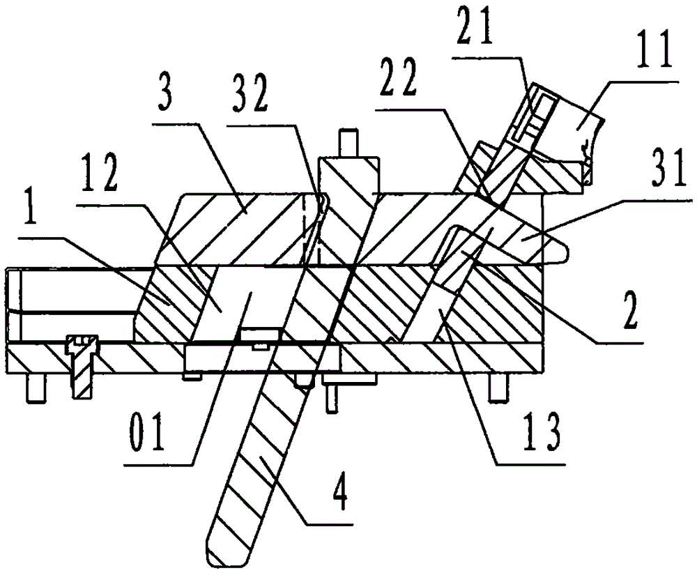
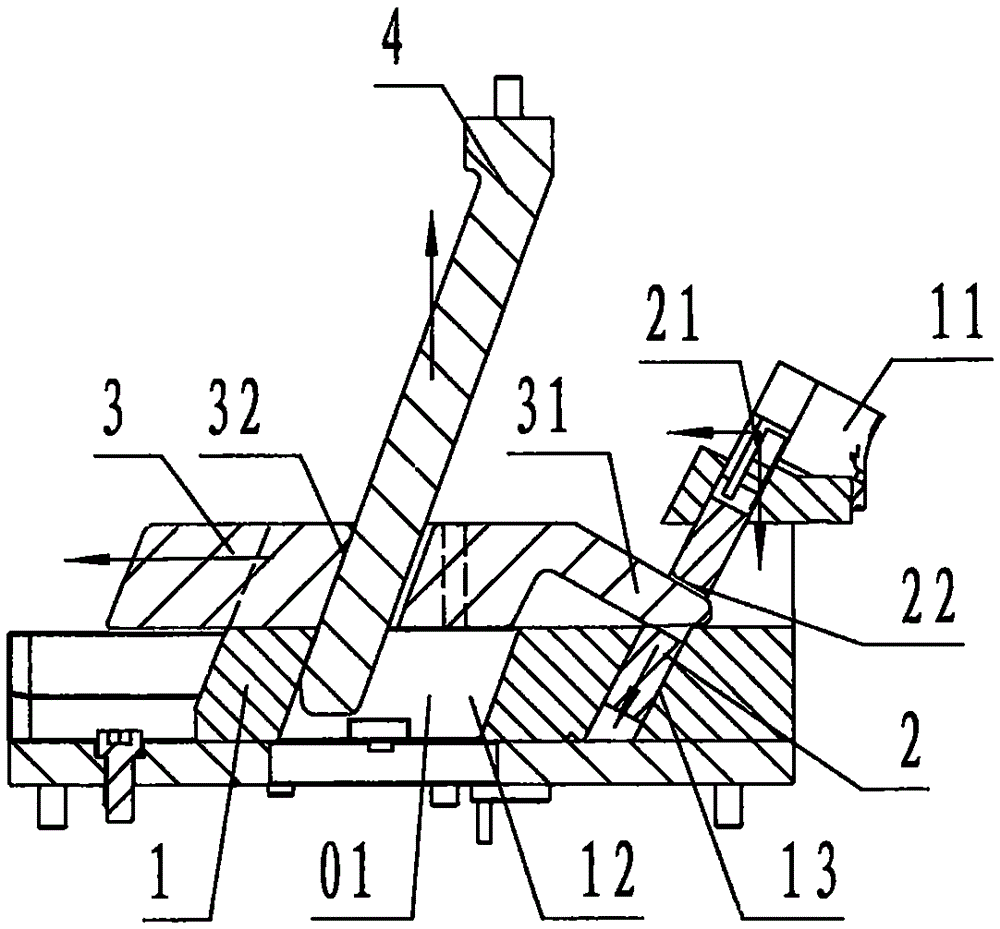
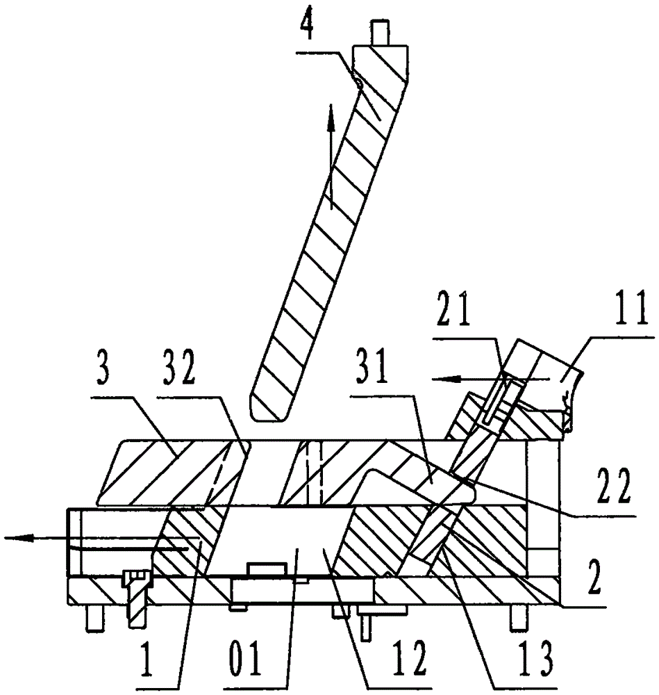
[0023] see Figure 1 ~ Figure 4 , an injection mold single-slider multi-direction combined core-pulling device of the present invention includes a transverse sliding block 1, an oblique sliding block 2, an oblique-pulling drive block 3, and a transverse-pulling and inclined guide column 4, wherein: the said The horizontal slider 1 is a rectangular block-shaped steel member. The left part of the horizontal slider 1 is provided with a through hole sloping from top to bottom to the left, which is called A inclined guide hole 12, and the right part of the horizontal slider 1 is provided with a The through hole inclined from top to bottom to the left is called the B inclined guide hole 13. The right side of the lateral slider 1 is provided with a horizontal core 11 that protrudes upward. The upper and right sides of the horizontal core 11 are provided with convex shapes corresponding to the product The concave surface corresponding to the surface;

[0024] The oblique sliding bloc...


PUM


Abstract

The invention discloses a multi-direction sequential combined core-pulling device for a single slide block of an injection mould. The multi-direction sequential combined core-pulling device comprises a transverse slide block (1), an inclined slide block (2), an inclined pulling drive block (3) and a transverse pulling inclined guide post (4). The transverse slide block is provided with an inclined guide hole A, an inclined guide hole B and a transverse pulling core; the inclined slide block is provided with an inclined pulling core and a pulling hole; the inclined pulling drive block is provided with an inclined pulling finger and an inclined guide hole C; the length, in the left-right direction, of the inclined guide hole A is greater than that of the inclined guide hole C, and the difference between the length, in the left-right direction, of the inclined guide hole A and the length, in the left-right direction, of the inclined guide hole C is defined as delay spacing; the transverse pulling inclined guide post is fixedly connected to a fixed mould, and the transverse slide block is in sliding connection to a movable mould; during mould closing, the delay spacing is positioned on the left part of the inclined guide hole A; by adopting the technical scheme that the transverse pulling inclined guide post firstly drives the inclined pulling drive block to drive the inclined slide block for pulling out the inclined pulling core in an inclined mode via the inclined pulling finger, then, when the delay spacing is moved to the right part of the inclined guide hole A, the transverse pulling inclined guide post drives the inclined pulling drive block and the transverse slide block to synchronously move for pulling out the transverse pulling core, so that the injection mould with narrow multi-direction sequential core-pulling achieves the purposes of simplifying the structure, reducing the body, reducing the cost and reducing faults.

Description

technical field [0001] The invention relates to a core-pulling and demoulding device for an injection mold, in particular to a single-slider multi-directional injection mold that realizes the combined core-pulling and demoulding in the first oblique direction and then the transverse direction on a single lateral slider of the injection mold. Combine the core-pulling devices in sequence. Background technique [0002] The core pulling and demolding of the injection mold is divided into longitudinal, transverse and oblique directions. The so-called longitudinal direction is along the opening and closing direction of the injection mold, the so-called transverse direction is the direction orthogonal to the longitudinal direction, and the so-called oblique direction is between the longitudinal direction and the transverse direction. direction. The lateral slider of the injection mold usually refers to the edge set on the movable mold carrier plate of the mold. Using the opening a...

Claims


Application Information

Patent Timeline
Patent Type & Authority Applications(China)
IPC IPC(8): B29C45/33B29C45/40
CPCB29C45/33B29C45/332B29C45/40
Inventor 顾来法雷万里储吉江邬亚东袁贤飞
Owner NINGBO SHUANGLIN MOULD CO LTD
Why Eureka
Try Eureka