Eureka AIR delivers breakthrough ideas for toughest innovation challenges, trusted by R&D personnel around the world.

Driving axle shell

A technology for driving axle housings and axle housings, which is applied in the directions of axles, wheels, transportation and packaging, etc. It can solve the problems of many wheel end mechanisms failures, short service life, poor heat dissipation of wheel end mechanisms, high temperature oil and gas, etc., and achieves good cooling effect , The effect of simple and convenient production and simple structure

Active Publication Date: 2016-06-08
DONGFENG COMML VEHICLE CO LTD
View PDF7 Cites 6 Cited by
  • Summary
  • Abstract
  • Description
  • Claims
  • Application Information

AI Technical Summary

Problems solved by technology

[0006] The purpose of the present invention is to solve the problem that the existing wheel end mechanism has poor heat dissipation and easy to generate high temperature oil gas, which leads to more faults and short service life of the wheel end mechanism, and provides a method that can effectively reduce the internal temperature of the wheel end mechanism and prolong the wheel end mechanism. The driving axle housing with the service life of the mechanism and its surrounding components is simple in structure, low in cost, easy to manufacture, and has a significant cooling effect on the wheel end mechanism

Method used


Image

  • Driving axle shell
  • Driving axle shell
  • Driving axle shell

Examples


Embodiment 1

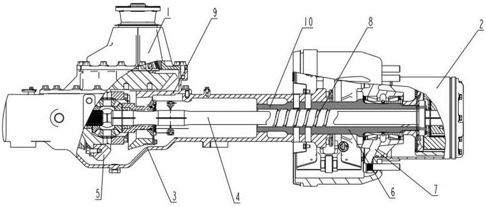
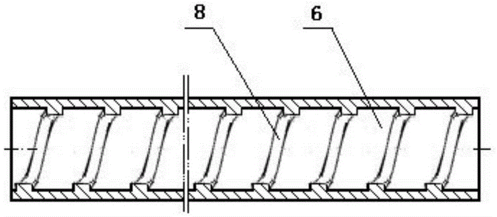
[0031] see figure 1 , the drive axle housing described in the present invention includes the axle housing in the middle and the final reducer housing 9 and the shaft tube parts 10 at both ends, and the axle shaft 4 can be installed in the shaft tube part 10, and the shaft tube part 10 A helical structure 8 is provided on the surface of the inner hole, and the helical structure 8 is a single-headed helical rib, and when the axle shaft 4 installed in the shaft tube part 10 rotates due to driving the drive axle and the vehicle forward , the direction in which the helical structure 8 axially transports lubricating oil points to one end of the final reducer 1 . The direction of rotation of the spiral structure 11 can be judged according to the left-hand and right-hand rules of the existing spiral material delivery direction. The direction of material delivery, the direction held by the four fingers is the direction of shaft rotation, and the direction of rotation of the helical s...

Embodiment 2

[0038] see Figure 4 , combined with figure 1 , figure 2 , the drive axle housing 3 is expanded into a form axle housing, the middle part of the drive axle housing 3 is expanded, and the two ends are steel pipes that have been thinned by rolling. At this time, the shaft tube part 10 is thinned by rolling steel pipe, that is, the inner hole of the shaft tube part 10 is a variable cross-section hole, and a helical structure 8 is arranged on the inner hole surface of the steel pipe, and the helical structure 8 is a spiral structure 8 hovering on the shaft tube part, that is, the inner hole surface of the steel pipe. Single-headed helical ribs, on the shaft tube portion 10 at both ends of the drive axle housing 3, the direction of rotation of the helical structure is opposite, that is, Figure 4 The forward direction of drive axle 3 shown in is the direction away from the reader, Figure 4 The direction of rotation of the helical structure 8 on the right axle tube portion 10 ...

Embodiment 3

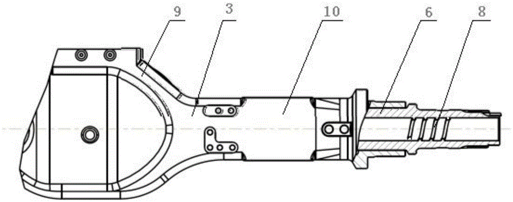
[0041] see image 3 , combined with figure 1 , figure 2 , the drive axle housing is a stamped and welded axle housing, and the axle housing is composed of the main parts of the axle housing, the leaf spring seat, the half shaft sleeve, the rear cover, etc. At this time, the shaft tube part 10 may include the half shaft A part of the overhanging section of the bushing and the main part of the axle housing can also directly use the half bushing as the shaft tube part 10, that is, the inner hole of the shaft tube part 10 is a hole of equal section, and the half shaft bushing A helical structure 8 is provided on the surface of the inner hole, and the helical structure 8 is a single-headed helical groove hovering on the surface of the inner hole of the shaft tube part 10, that is, the half-axle sleeve. 10, the direction of the helical structure is opposite, that is, image 3 The forward direction of drive axle 3 shown in is the direction away from the reader, image 3 The dir...


PUM


Abstract

Disclosed is a driving axle shell. The driving axle shell comprises an axle shell body, a main speed reducer shell (9) and axle tube parts (10). The axle shell body and the main speed reducer shell (9) are arranged in the middle, and the axle tube parts (10) are arranged at the two ends correspondingly. A half axle (4) can be installed in an inner hole of each axle tube part (10). The surface of the inner hole of each axle tube part (10) is provided with a spiral structure (8). Each spiral structure (8) is a single-head or multiple-head spiral flange or spiral groove. In addition, when the half axles (4) installed in the inner holes of the axle tube parts (10) rotate in order to drive a wheel hub (7) and a vehicle to go forwards, the direction of lubricating oil conveying through the spiral structures (8) points to one side of a main speed reducer (1). The structure is simple, the design is novel, and manufacturing is simple and convenient. The oil quantity in all cavities can be kept stable, sufficient lubrication of all components is ensured, and oil gas discharging and cooling effects on a wheel end mechanism (2) are particularly good. The service life of a driving axle system is effectively prolonged, and the driving axle shell can be suitable for all driving axles of which the wheel end mechanisms adopt oil lubrication.

Description

technical field [0001] The invention relates to a driving axle housing, in particular to a driving axle housing in which a wheel end mechanism is lubricated by oil. Background technique [0002] The drive axle is at the end of the power train, and the torque from the engine is transmitted to the drive wheels through the drive axle to realize the rotation of the wheels. For single-stage drive axles, oil lubrication is mainly used for wheel end bearings. For wheel-side reduction drive axles, both hub bearings and wheel-side reducers need to be considered for oil lubrication. [0003] Existing drive axles such as the wheel side reduction drive axle of Dongfeng Commercial Vehicle Co., Ltd., such as Figure 5 , mainly including the main reducer 1, the wheel end mechanism 2, the drive axle housing 3, the half shaft 4, the driven bevel gear 5, the shaft tube 6 and the hub 7, and the said main reducer 1 includes the driving bevel gear and the driven cone The gear 5 and the driven b...

Claims


Application Information

Patent Timeline
Patent Type & Authority Applications(China)
IPC IPC(8): B60B35/14B60B35/16B60B35/12
CPCB60B35/121B60B35/14B60B35/163
Inventor 刘春立陈永华蒋鸣刘金胡凯刘伟邢红岩张红星
Owner DONGFENG COMML VEHICLE CO LTD
Why Eureka
Eureka Blog
Learn More