Half axle for vehicle

A vehicle and axle body technology, which is applied in the directions of axles, axles, wheels, etc., can solve the problems of poor heat dissipation of the wheel end mechanism, high temperature oil and gas, increased temperature of the wheel end mechanism, and short service life, and achieves the effect of exhaust and heat dissipation. Enhancement, increased heat generation, and improved service life

Active Publication Date: 2016-05-25
DONGFENG COMML VEHICLE CO LTD
View PDF5 Cites 2 Cited by
  • Summary
  • Abstract
  • Description
  • Claims
  • Application Information

AI Technical Summary

Problems solved by technology

[0006] The purpose of the present invention is to solve the problem of poor heat dissipation of the wheel end mechanism on the existing drive axle assembly, easy to generate high temperature oil and gas, resulting in temperature rise of the wheel end mechanism, many faults, and short service life, and to provide a method that can effectively reduce The internal temperature of the wheel end mechanism is a vehicle half shaft that prolongs the service life of the wheel end mechanism and its surrounding components. It has a simple structure, low cost, and is easy to manufacture. It has a significant cooling effect on the wheel end mechanism.

Method used


Image

  • Half axle for vehicle
  • Half axle for vehicle
  • Half axle for vehicle

Examples


Embodiment 1

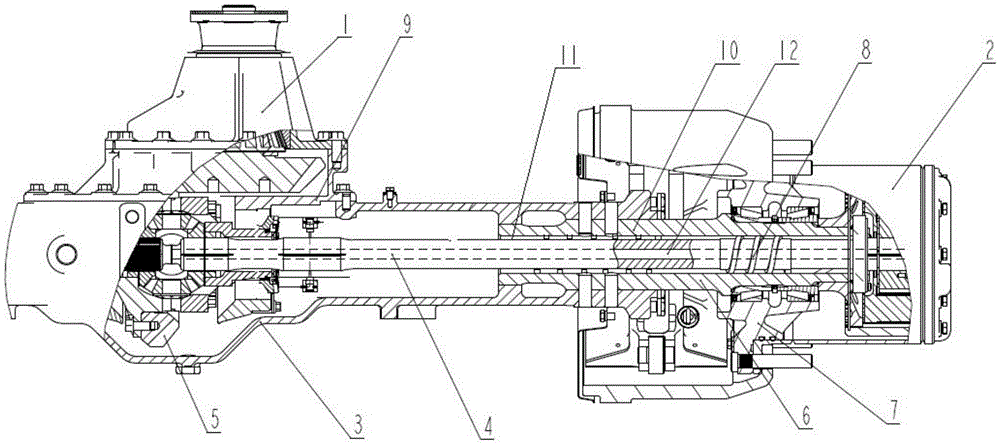
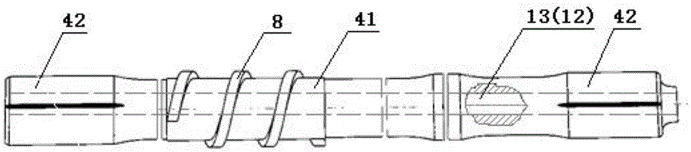
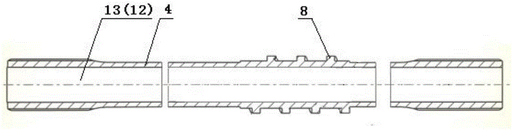
[0059] see figure 1 , figure 2 , image 3 , Figure 12 , the structure in which the half shaft 4 of the first structure of the present invention cooperates with the first shaft tube part 10, the vehicle half shaft of the present invention adopts figure 1 Axis 4 shown and figure 2 , image 3 The structure of the shaft body 41 shown in the figure and the key connection part 42, the outer surface of the shaft body 41 is provided with a helical structure 8, the center of the shaft body 41 is provided with a hollow inner hole that runs through the entire length, that is, the shaft inner channel 12, and the shaft body 41 The left end of the upper hollow inner hole leads to the wheel end mechanism 2, and the right end leads to the final reducer 1. The hollow inner hole is the diameter of the channel 12 in the shaft and the helical structure 8 in it so that the flow rate of the lubricating liquid through the hollow inner hole is slightly smaller than that of the shaft. The fl...

Embodiment 2

[0063] see Figure 13 , combined with figure 1 , Figure 4, is the structure that the half shaft 4 of the second structure of the present invention cooperates with the first shaft tube part 10; A helical structure 8 is provided in the inner hole, that is, the inner channel 12 of the shaft. The helical structure 8 is a single-headed or multi-headed spiral rib or spiral groove arranged in the shaft body 41 and the inner shaft hole 13 of the half shaft 4. As a result, there are two sets of helical structures 8 on the half shaft 4, one set of helical structures 8 is set on the outer surface of the half shaft 4, and the other set of helical structures 8 is set in the inner channel 12 of the shaft, and when the shaft body 41 rotates, The two groups of helical structures 8 transport lubricating liquid in opposite directions.

Embodiment 3

[0065] see Figure 14 , combined with figure 1 , the structure in which the half shaft 4 of the first structure of the present invention cooperates with the shaft tube part 10 of the second type. The structure of the half shaft 4 in this embodiment is exactly the same as that in Embodiment 1, but the half shaft sleeve 6 is different from that of Embodiment 1. A group of helical structures 8 are also arranged in the inner hole of the half shaft sleeve 6 in this embodiment. The set of helical structures 8 has the same helical direction as the helical structures 8 on the outer surface of the half shaft 4 . Other structures in this embodiment are basically the same as those in Embodiment 1.


PUM


Abstract

The invention discloses a half axle for a vehicle. The half axle comprises an axle body (41) and key connection portions (42) located at the two ends of the axle body (41). An axle inner channel (12) is arranged below the outer surface of the axle body (41). The outer surface or the axle inner channel (12) of the axle body (41) is provided with a spiral structure. When the axle body (41) rotates to drive a hub (7) or a vehicle to move forwards, the spiral structure (8) outputs lubricating liquid towards one side of a main speed reducer (1); or the outer surface and the axle inner channel (12) of the axle body (41) are each provided with a spiral structure (8), and circular flow of lubricating liquid in a driving axle is propelled. The half axle is simple in structure, novel in design, easy and convenient to manufacture, capable of ensuring stability of the oil quantity in each cavity and ensuring that the all the components are sufficiently lubricated, particularly good in oil gas exhaust effect and cooling effect on a wheel end mechanism (2) and applicable to all driving axles with wheel end mechanisms adopting lubricating oil, and the service life of a driving axle system is effectively prolonged.

Description

technical field [0001] The invention relates to a half shaft for a vehicle, in particular to a half shaft for a vehicle used for a drive axle with oil lubrication as a wheel end mechanism. Background technique [0002] The drive axle is at the end of the power train, and the torque from the engine is transmitted to the drive wheels through the drive axle to realize the rotation of the wheels. For single-stage drive axles, oil lubrication is mainly used for wheel end bearings. For wheel-side reduction drive axles, both hub bearings and wheel-side reducers need to be considered for oil lubrication. [0003] Existing drive axles such as the wheel-side reduction drive axles adopted by Dongfeng Commercial Vehicle Co., Ltd., such as Figure 18 , mainly including the main reducer 1, the wheel end mechanism 2, the drive axle housing 3, the half shaft 4, the driven bevel gear 5, the shaft tube 6 and the hub 7, and the said main reducer 1 includes the driving bevel gear and the driven...

Claims


Application Information

Patent Timeline
Patent Type & Authority Applications(China)
IPC IPC(8): B60B35/14F16C3/02
CPCB60B35/14B60B2900/513B60B2900/561F16C3/02
Inventor 刘春立陈永华蒋鸣刘金胡凯刘伟邢红岩张红星
Owner DONGFENG COMML VEHICLE CO LTD
Why Eureka
Try Eureka