Rotary pay-off rack

A technology of rotating frame and pay-off frame, which is applied in the direction of conveying filamentous materials, thin material processing, transportation and packaging, etc. It can solve the problems of time-consuming and labor-intensive pay-off frames, low production efficiency, and dead bends, etc., and achieves convenient operation , High production efficiency and smooth wire release

Inactive Publication Date: 2016-06-08
THE NORTHWEST MACHINE
View PDF0 Cites 3 Cited by
  • Summary
  • Abstract
  • Description
  • Claims
  • Application Information

AI Technical Summary

Problems solved by technology

[0003] The purpose of the present invention is to overcome the deficiencies in the above-mentioned prior art, and provide a rotary pay-off stand, which has a compact structure and is safe and reliable

Method used


Image

  • Rotary pay-off rack
  • Rotary pay-off rack
  • Rotary pay-off rack

Examples


Example Embodiment

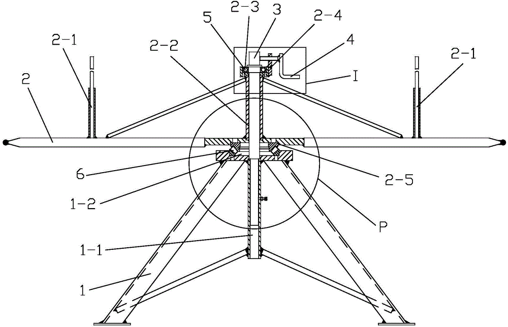
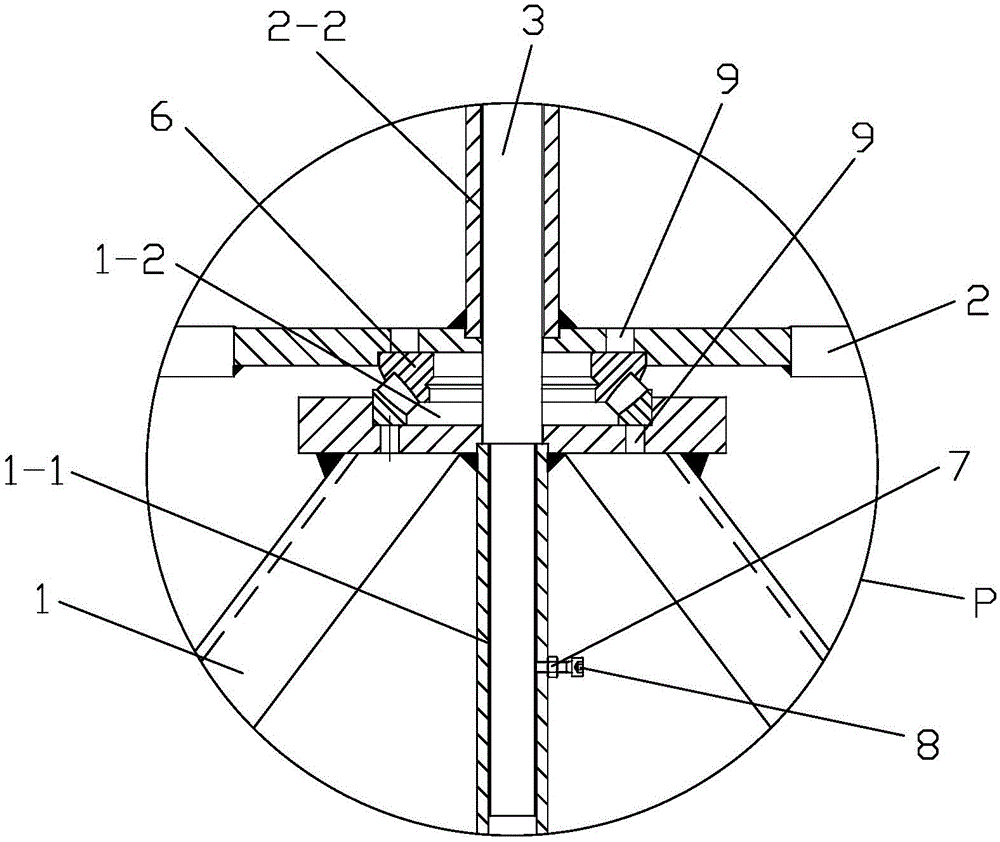
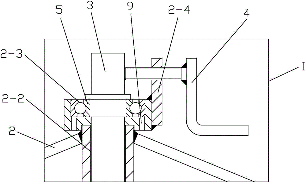
[0028] like Figure 1 to Figure 4 As shown, the present invention comprises a base 1, a swivel frame 2, a shaft 3 and a handle 4, the swivel frame 2 is arranged above the base 1, and the top of the swivel frame 2 is fixed with a plurality of retaining rods 2-1, and a plurality of A wire retaining rod 2-1 forms a wire coil placement column for placing wire coils, the base 1 is provided with a first hole 1-1 along the central axis, and the rotating frame 2 is provided with a second hole along the central axis 2-2, the upper end surface of the base 1 has a first groove 1-2, the lower end surface of the rotating frame 2 has a third groove 2-5, and the base 1 and the rotating frame 2 are provided There is a second bearing 6, the outer ring of the second bearing 6 is tightly fitted with the first groove 1-2, the inner ring of the second bearing 6 is tightly fitted with the third groove 2-5, and the rotating frame The upper end surface of 2 has a second groove 2-3, and the first bea...


PUM


Abstract

The invention discloses a rotary pay-off rack. The rotary pay-off rack comprises a base, a rotary rack body, a shaft and a handle. The rotary rack body is arranged on the base. Wire blocking rods are fixed to the top of the rotary rack body. A first hole is formed in the base. A second hole is formed in the rotary rack body. A first groove is formed in the upper end face of the base. A third groove is formed in the lower end face of the rotary rack body. A second bearing is arranged between the base and the rotary rack body. The outer ring of the second bearing is in close fit with the first groove. The inner ring of the second bearing is in close fit with the third groove. A second groove is formed in the upper end face of the rotary rack body. A first bearing is arranged in the second groove. The shaft stretches into the first hole after sequentially penetrating through the first bearing, the second hole and the second bearing from top to bottom. A bolt is arranged on the base, and the end of the bolt abuts against the shaft. A nut is arranged on the bolt. A plate is fixed to the right side of the top of the rotary rack body. The handle penetrates through the plate, and the end of the handle abuts against the shaft. The rotary pay-off rack is compact in structure and safe and reliable in use, and the problems that according to an existing pay-off rack, time consumption and labor consumption are large, wires are out of order, fast knots are caused, the production efficiency is low, and the noise is high are solved.

Description

technical field [0001] The invention belongs to the technical field of cable equipment, and in particular relates to a rotary pay-off frame. Background technique [0002] The existing pay-off frame is a vertical structure, that is, through a waist-drum-shaped pay-off device, the wire is wound from the waist-drum-shaped device, and then led down to enter the next equipment. The pay-off frame of this structure has the following disadvantages in use: (1) because it is a vertical structure, it needs a very high vertical height to straighten the wire through the gravity of the wire itself; (2) the wire and the waist drum sometimes Rolling friction and sometimes sliding friction can easily scratch the surface of the wire and affect the deep processing of the wire; (3) There is no fixed track for the wire to walk on the waist drum. , that is, rebound and jump out of the edge of the waist drum, causing the wire to get stuck in the gap or fall off the waist drum, causing the wire to...

Claims


Application Information

Patent Timeline
IPC IPC(8): B65H49/32
Inventor 罗曦耀李安
Owner THE NORTHWEST MACHINE
Why Eureka
Try Eureka