A toilet with a high-efficiency flushing water circuit

A toilet and waterway technology, applied in flushing toilets, water supply devices, buildings, etc., can solve problems such as not easy to outline a smooth waterway, affect flushing function, short steering stroke, etc., achieve good dredging effect and improve water flow energy , Increase the effect of steering stroke

Active Publication Date: 2017-11-24
XIAMEN R&T PLUMBING TECH
View PDF9 Cites 0 Cited by
  • Summary
  • Abstract
  • Description
  • Claims
  • Application Information

AI Technical Summary

Problems solved by technology

[0002] like figure 1 and figure 2 As shown, the main flush part of the existing common flushing waterway of the toilet generally includes a horizontal diversion section 10', an inclined diversion section 20' and a turning jet section 40', and the water flow first flows along the horizontal diversion section 10' on the toilet seat body. It flows from back to front, then gradually descends along the inclined diversion section 20' and tilts forward to reach the front of the toilet sewage outlet, then the water flow direction turns 180 degrees, and the sewage is discharged from the turning jet section 40' towards the toilet. The 180-degree turn of the flushing waterway has a long overall stroke and a short steering stroke, which increases the potential energy loss of the water during the flow process and affects the overall flushing function. Moreover, the waterway is easily affected by the appearance of the toilet. It is easy to outline a relatively smooth waterway, and there is instability in the mass production of toilets

Method used


Image

  • A toilet with a high-efficiency flushing water circuit
  • A toilet with a high-efficiency flushing water circuit
  • A toilet with a high-efficiency flushing water circuit

Examples


Embodiment Construction

[0029] In order to make the technical problems, technical solutions and beneficial effects to be solved by the present invention clearer and clearer, the present invention will be further described in detail below in conjunction with the accompanying drawings and embodiments. It should be understood that the specific embodiments described here are only used to explain the present invention, not to limit the present invention.

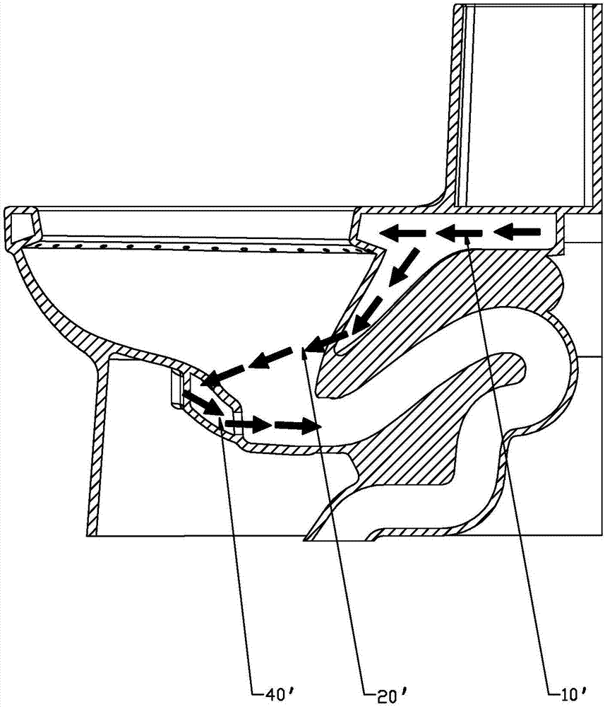
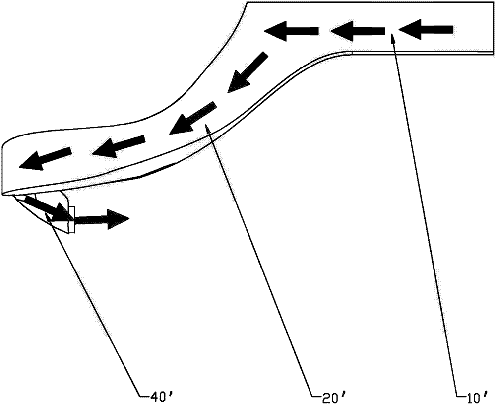
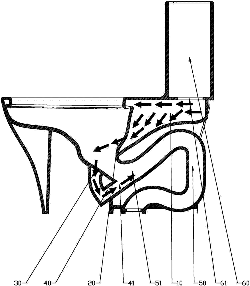
[0030] Such as image 3 and Figure 4 As shown, a toilet with a high-efficiency flushing waterway of the present invention includes a jetting waterway supplying water to the jetting port 41 of the toilet and a sewage drainage way 50 connected to the sewage outlet 51 of the toilet. In this embodiment, the drainage channel 50 adopts a siphon channel with double traps. The spraying water path includes a horizontal diversion section 10 , an inclined diversion section 20 , a discharge section 30 and a jet section 40 which are sequentially connected.

[00...


PUM


Abstract

A toilet having a high-efficiency flush passage, comprising a jet passage providing water for a jet port (41) of a toilet and a trapway passage (50) connected to a trapway port (51) of the toilet. The jet passage comprises a flow guide section, a flow discharge section (30), and a flow jet section (40) that are sequentially in communication with each other. A first turning corner is provided between the flow guide section and the flow discharge section (30), and a second turning corner is provided between the flow discharge section (30) and the flow jet section (40). The flow discharge section (30) vertically extends downward, and the flow discharge section (30) and the trapway passage (50) are respectively provided on the front and rear sides of the trapway port (51). After flowing through the flow guide section, water enters the flow discharge section (30) by means of the first turning corner, enters the flow jet section (40) from the flow discharge section (30) by means of the second turning corner, and is finally jetted to the trapway port (51) from the jet port (41) of the toilet.

Description

technical field [0001] The invention relates to a toilet with a high-efficiency flushing water circuit. Background technique [0002] Such as figure 1 and figure 2 As shown, the main flush part of the existing common flushing waterway of the toilet generally includes a horizontal diversion section 10', an inclined diversion section 20' and a turning jet section 40', and the water flow first flows along the horizontal diversion section 10' on the toilet seat body. It flows from back to front, then gradually descends along the inclined diversion section 20' and tilts forward to reach the front of the toilet sewage outlet, then the water flow direction turns 180 degrees, and the sewage is discharged from the turning jet section 40' towards the toilet. The 180-degree turn of the flushing waterway has a long overall stroke and a short steering stroke, which increases the potential energy loss of the water during the flow process and affects the overall flushing function. Moreo...

Claims


Application Information

Patent Timeline
Patent Type & Authority Patents(China)
IPC IPC(8): E03D11/06E03D11/16E03D11/17
CPCE03D11/06E03D11/13E03D11/17
Inventor 钟志军刘梓光陈海滨
Owner XIAMEN R&T PLUMBING TECH
Why Eureka
Try Eureka