Locking device used for electronic-control-free well lid lock and having stable gear maintaining function

A locking device and manhole cover technology, applied in non-mechanical transmission-operated locks, construction locks, construction and other directions, can solve the problems of short lock life, high cost, failure, etc., and achieve the effect of avoiding unmaintainable and simple structure

Active Publication Date: 2016-06-08
康威通信技术股份有限公司
View PDF6 Cites 1 Cited by
  • Summary
  • Abstract
  • Description
  • Claims
  • Application Information

AI Technical Summary

Problems solved by technology

The failure of the manhole cover lock is nothing more than that it cannot be opened, or it cannot be locked, or the life of the lock is short. These are the results that the manhole cover manager does not want to see
The way to realize the two-speed maintenance of locking and opening is traditionally through the method of spring top ball, tension spring

Method used


Image

  • Locking device used for electronic-control-free well lid lock and having stable gear maintaining function
  • Locking device used for electronic-control-free well lid lock and having stable gear maintaining function
  • Locking device used for electronic-control-free well lid lock and having stable gear maintaining function

Examples


Embodiment 1

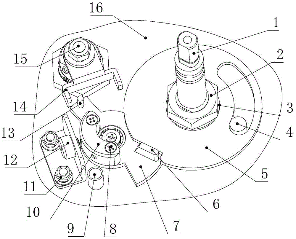
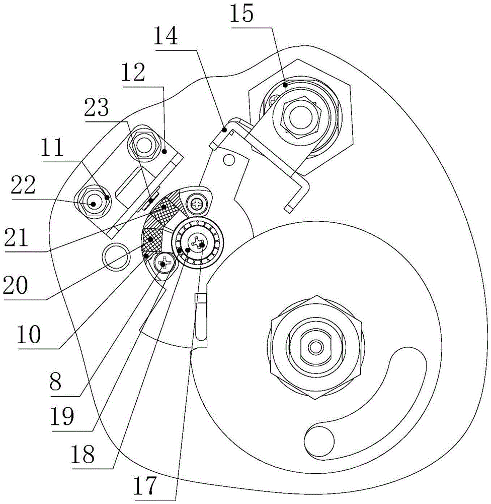
[0027] The locking device applied to the manhole cover lock without electric control to stably maintain the gear position includes a lock case 16, a main shaft 1 is arranged on the lock case 16, the top of the main shaft 1 is connected with the manhole cover, and the bottom end of the main shaft 1 is movable with a locking device. Disc 5, between chuck 5 and lock housing 16 is provided with the stopper mechanism that is used to stop chuck 5 rotations after chuck 5 rotates setting angle, is provided with chuck connecting rod 7 movablely on lock housing 16, clamps One end of the disc connecting rod 7 is provided with a top block 6 for stopping the rotation of the chuck 5, and the other end of the chuck connecting rod 7 is provided with a stop pin 13 for driving the rotation of the chuck connecting rod 7. There are two first magnets (magnet A20 and magnet B21) at a set distance, and a second magnet (magnet C23) is arranged on the lock housing 16. After the chuck connecting rod 7 r...

Embodiment 2

[0039] The locking device applied to the manhole cover lock without electric control to stably maintain the gear position includes a lock case 16, a main shaft 1 is arranged on the lock case 16, the top of the main shaft 1 is connected with the manhole cover, and the bottom end of the main shaft 1 is movable with a locking device. Disc 5, between chuck 5 and lock housing 16 is provided with the stopper mechanism that is used to stop chuck 5 rotations after chuck 5 rotates setting angle, is provided with chuck connecting rod 7 movablely on lock housing 16, clamps One end of the disc connecting rod 7 is provided with a top block 6 for stopping the rotation of the chuck 5, and the other end of the chuck connecting rod 7 is provided with a stop pin 13 for driving the rotation of the chuck connecting rod 7. There are two first magnets (magnet A20 and magnet B21) at a set distance, and a second magnet (magnet C23) is arranged on the lock housing 16. After the chuck connecting rod 7 r...


PUM


Abstract

The invention discloses a locking device used for an electronic-control-free well lid lock and having a stable gear maintaining function. The locking device comprises a lock case, wherein a spindle is arranged on the lock case; the top end of the spindle is connected with a well lid; a chuck is movably arranged at the bottom end of the spindle; a stopping mechanism which is used for stopping rotation of the chuck after the chuck rotates at a set angle is arranged between the chuck and the lock case; a chuck connecting rod is movably arranged on the lock case; an ejector block which is used for pushing the chuck to rotate is arranged at one end of the chuck connecting rod; a stop pin which is used for driving the chuck connecting rod to rotate is arranged at the other end of the chuck connecting rod; two first magnets which are spaced from each other by a set distance are arranged on the chuck connecting rod; and a second magnet is arranged on the lock case. The locking device has the beneficial effect that magnetic maintaining is implemented, a spring bolt with a forked corner piece shifts to change the positions of the two first magnets so as to achieve the purpose of stably maintaining an unlocking state and a locking state, an electromagnet is not required, the structure is simple, and the circumstance that the electromagnet which is not electrified cannot maintain the unlocking state and the locking state is avoided.

Description

technical field [0001] The invention relates to a well cover locking device, in particular to a locking device applied to a non-electrically controlled well cover lock for stably maintaining gear positions. Background technique [0002] Manhole cover locks applied to urban pipelines are critical to maintaining the state when they are in the open or closed state. The failure of the manhole cover lock is nothing more than that it cannot be opened, or it cannot be locked, or the life of the lock is short. These are the results that the manhole cover manager does not want to see. The way to realize the two-speed maintenance of locking and opening is traditionally through the method of spring top ball, tension spring, and electromagnet. The first two methods are purely mechanical, and the life is limited by the life of the spring. Once the spring is corroded and broken, the lock The function of the electromagnet is invalid; the electromagnet method is an electronic control metho...

Claims


Application Information

Patent Timeline
IPC IPC(8): E05B65/00E05B47/00
CPCE05B47/0038E05B65/00
Inventor 杨震威姜志利
Owner 康威通信技术股份有限公司
Why Eureka
Try Eureka