
Wind volume and wind pressure sensing and pressure receiving device

A receiver and wind pressure technology, which is applied in the field of air volume and pressure sensing and pressure receivers, can solve the problems of low reading accuracy, affecting airflow reading accuracy, failing to achieve energy saving and precise control, etc.

Inactive Publication Date: 2016-06-08
广东康美风通风设备有限公司
View PDF10 Cites 0 Cited by
  • Summary
  • Abstract
  • Description
  • Claims
  • Application Information

AI Technical Summary

Problems solved by technology

When in use, the air volume and air pressure sensor and pressure receiver are installed in a circular pipe; due to the limitation of the shape of the aluminum pipe itself, the hole diameter and hole spacing are not uniform, which affects the airflow reading accuracy and cannot accurately measure the airflow guide. The reading accuracy of the air volume and air pressure on the flow surface is not high, the indoor temperature cannot be accurately controlled, and the purpose of energy saving and precise control cannot be achieved

Method used


Image

  • Wind volume and wind pressure sensing and pressure receiving device
  • Wind volume and wind pressure sensing and pressure receiving device
  • Wind volume and wind pressure sensing and pressure receiving device

Examples


Embodiment 1

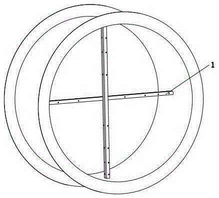
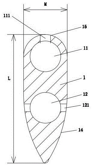
[0035] Such as Figure 1 to Figure 4As shown, it is an air volume and pressure sensing and pressure receiver, including two air volume and pressure sensing rods 1 installed on the air duct; the length of the air volume and wind pressure sensing rod 1 is 150 ± 0.2 mm, The cross-section of the wind pressure sensing rod 1 is in the shape of an airfoil, and the length L and width M of the cross-section of the wind pressure sensing rod 1 are 25 ± 0.2 mm and 8.5 ± 0.2 mm respectively; the top surface of the wind pressure sensing rod 1 is the windward side 15 , the windward surface 15 is arc-shaped, and its radius is 4.25 ± 0.2 mm; the left and right sides of the lower part of the air volume and pressure sensing rod 1 are inclined inwardly in an arc shape to form a wind-guiding surface 14, and the radius of the wind-guiding surface 14 is 24.7 ± 0.2 mm; in the air volume wind pressure sensing rod 1, there are windward induction flow channel 11 and wind guide induction flow channel 12,...

Embodiment 2

[0038] like figure 1 , figure 2 , Figure 5 and Image 6 As shown, it is a kind of air volume and wind pressure sensing and pressure receiver, including more than one air volume and wind pressure sensing rod 1 installed at the air duct; the length of the air volume and wind pressure sensing rod 1 is 180±0.2 mm, The section of the pressure sensing rod 1 is in the shape of an airfoil, and the length L and width M of the section of the air volume and wind pressure sensing rod 1 are respectively 25 ± 0.2 mm and 8.5 ± 0.2 mm; the top surface of the air volume and wind pressure sensing rod 1 is the windward side 15, The windward surface 15 is arc-shaped, and its radius is 4.25 ± 0.2 millimeters; the left and right sides of the lower part of the air volume and wind pressure sensing rod 1 are inclined inward in an arc shape to form a wind-guiding surface 14, and the radius of the wind-guiding surface 14 is 24.7±0.2 mm; windward induction flow channel 11 and wind guide induction fl...

Embodiment 3

[0041] like figure 1 , figure 2 , Figure 7 and Figure 8 As shown, it is an air volume and pressure sensing and pressure receiver, including more than one air volume and pressure sensing rod 1 installed at the air duct; the length of the air volume and wind pressure sensing rod 1 is 200 ± 0.2 mm, The section of the pressure sensing rod 1 is in the shape of an airfoil, and the length L and width M of the section of the air volume and wind pressure sensing rod 1 are respectively 25 ± 0.2 mm and 8.5 ± 0.2 mm; the top surface of the air volume and wind pressure sensing rod 1 is the windward side 15, The windward surface 15 is arc-shaped, and its radius is 4.25 ± 0.2 millimeters; the left and right sides of the lower part of the air volume and wind pressure sensing rod 1 are inclined inward in an arc shape to form a wind-guiding surface 14, and the radius of the wind-guiding surface 14 is 24.7±0.2 mm; windward induction flow channel 11 and wind guide induction flow channel 12 ...


PUM


Abstract

The invention relates to a wind volume and wind pressure sensing and pressure receiving device. The wind volume and wind pressure sensing and pressure receiving device is characterized by comprising more than one wind volume and wind pressure sensing rod installed at a wind duct; the sections of the wind volume and wind pressure sensing rods are in the shape of a wing; the top surfaces of the wind volume and wind pressure sensing rods serve as windward surfaces which are in an arch shape; the left sides and the right sides of the middle-lower portions of the wind volume and wind pressure sensing rods are inwards inclined in an arc shape to form wind guide surfaces; windward sensing flow channels and wind guide sensing flow channels are formed in the wind volume and wind pressure sensing rods; first windward openings, second windward openings, third windward openings and fourth windward openings are sequentially formed in the portions, located at the middle lines of the windward surfaces, of the wind volume and wind pressure sensing rods and communicated with the windward sensing flow channels; the portions, on the left side and the right side of each wind guide sensing flow channel, of the corresponding wind volume and wind pressure sensing rod are symmetrically provided with two first wind guide openings, two second wind guide openings, two third wind guide openings and two fourth wind guide openings respectively, and the first wind guide openings, the second wind guide openings, the third wind guide openings and the fourth wind guide openings are all communicated with the wind guide sensing flow channels and located on the middle lines of the wind guide sensing flow channels. The wind volume and wind pressure sensing and pressure receiving device has the advantages of being small in wind resistance and high in wind volume and wind pressure measurement precision.

Description

technical field [0001] The invention relates to an air volume wind pressure sensor and a pressure receiver. Background technique [0002] At present, air volume and air pressure sensors and pressure receivers are drilled through aluminum pipes. When in use, the air volume and air pressure sensor and pressure receiver are installed in a circular pipe; due to the limitation of the shape of the aluminum pipe itself, the hole diameter and hole spacing are not uniform, which affects the airflow reading accuracy and cannot accurately measure the airflow guide. The reading accuracy of the air volume and air pressure on the flow surface is not high, and the indoor temperature cannot be accurately controlled, which fails to achieve the purpose of energy saving and precise control. Contents of the invention [0003] The object of the present invention is to overcome the deficiencies of the prior art and provide an air volume and air pressure sensor and pressure receiver with small ...

Claims


Application Information

Patent Timeline
IPC IPC(8): G01D21/02
CPCG01D21/02
Inventor 王芬全
Owner 广东康美风通风设备有限公司
Learn More